Digitally-controlled oscillator with switched-capacitor frequency selection

a switched-capacitor, digital control technology, applied in the direction of pulse generator, pulse technique, electric pulse generator circuit, etc., can solve the problems of more significant redesign effort, power dissipation, and analog components are vulnerable to dc offset and drift phenomena

Inactive Publication Date: 2005-06-07
TEXAS INSTR INC
View PDF5 Cites 42 Cited by
  • Summary
  • Abstract
  • Description
  • Claims
  • Application Information

AI Technical Summary

Benefits of technology

[0016]It is therefore an object of the present invention to provide a digi...

Problems solved by technology

Secondly, analog components are vulnerable to DC offset and drift phenomena that are not present in equivalent digital implementations.
Furthermore, the loop dynamics of analog PLLs are quite sensitive to process technology scaling, whereas the behavior of digital logic remains unchanged with scaling; this requires much more significant redesign effort to migrate analog PLLs to a new technology node than is required for digital PLLs.
Moreover, power dissipation is of extreme concern for portable, battery-powered, computing systems, as power dissipation relates directly to battery life.
It has been observed, however, that a reduction in the power supply voltage applied to analog circuitry, such as analog or hybrid PLLs, does not necessarily reduce the power dissipated by these circuits; in some cases, aggressive voltage scaling has been observed to increase the power dissipated by analog circuits.
Additionally, reduction in the power s...

Method used


Image

  • Digitally-controlled oscillator with switched-capacitor frequency selection
  • Digitally-controlled oscillator with switched-capacitor frequency selection
  • Digitally-controlled oscillator with switched-capacitor frequency selection

Examples


Embodiment Construction

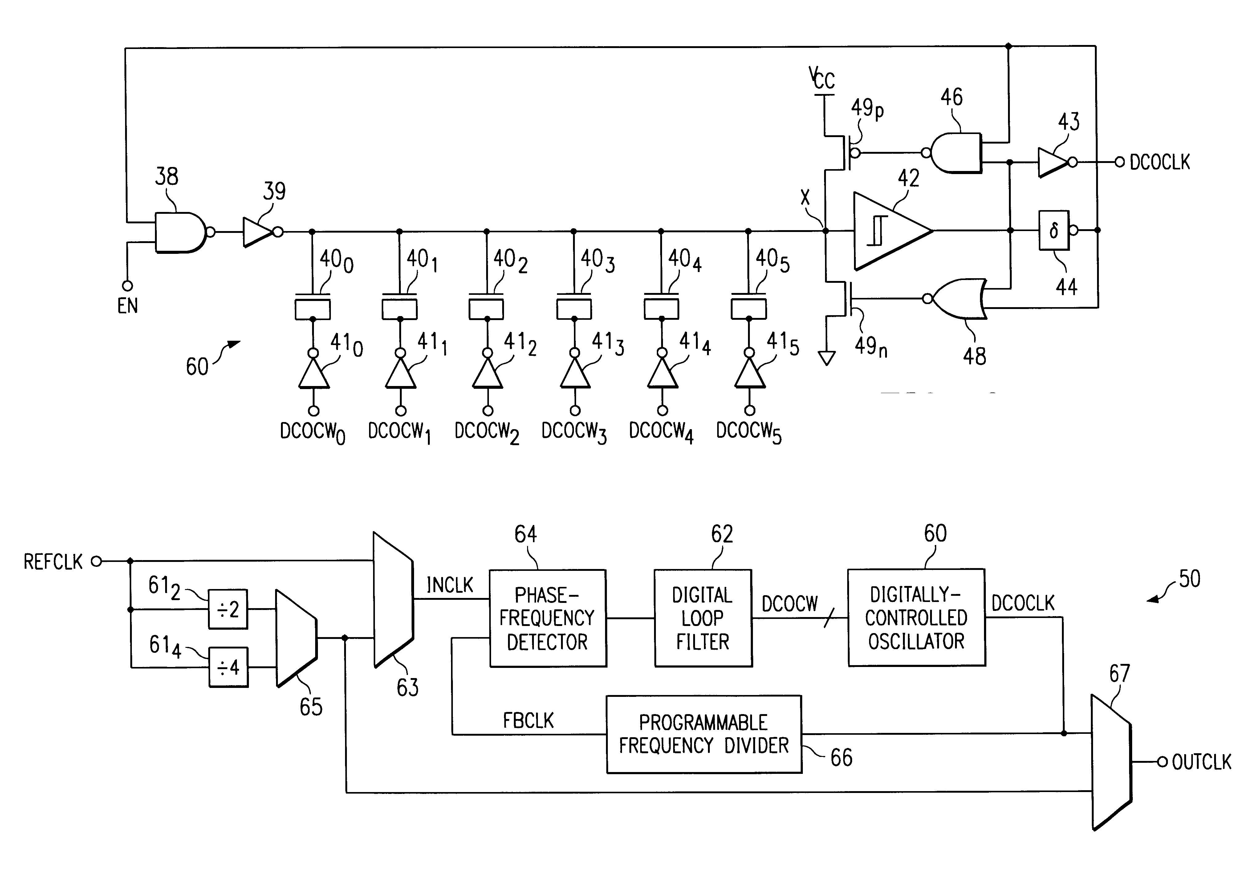
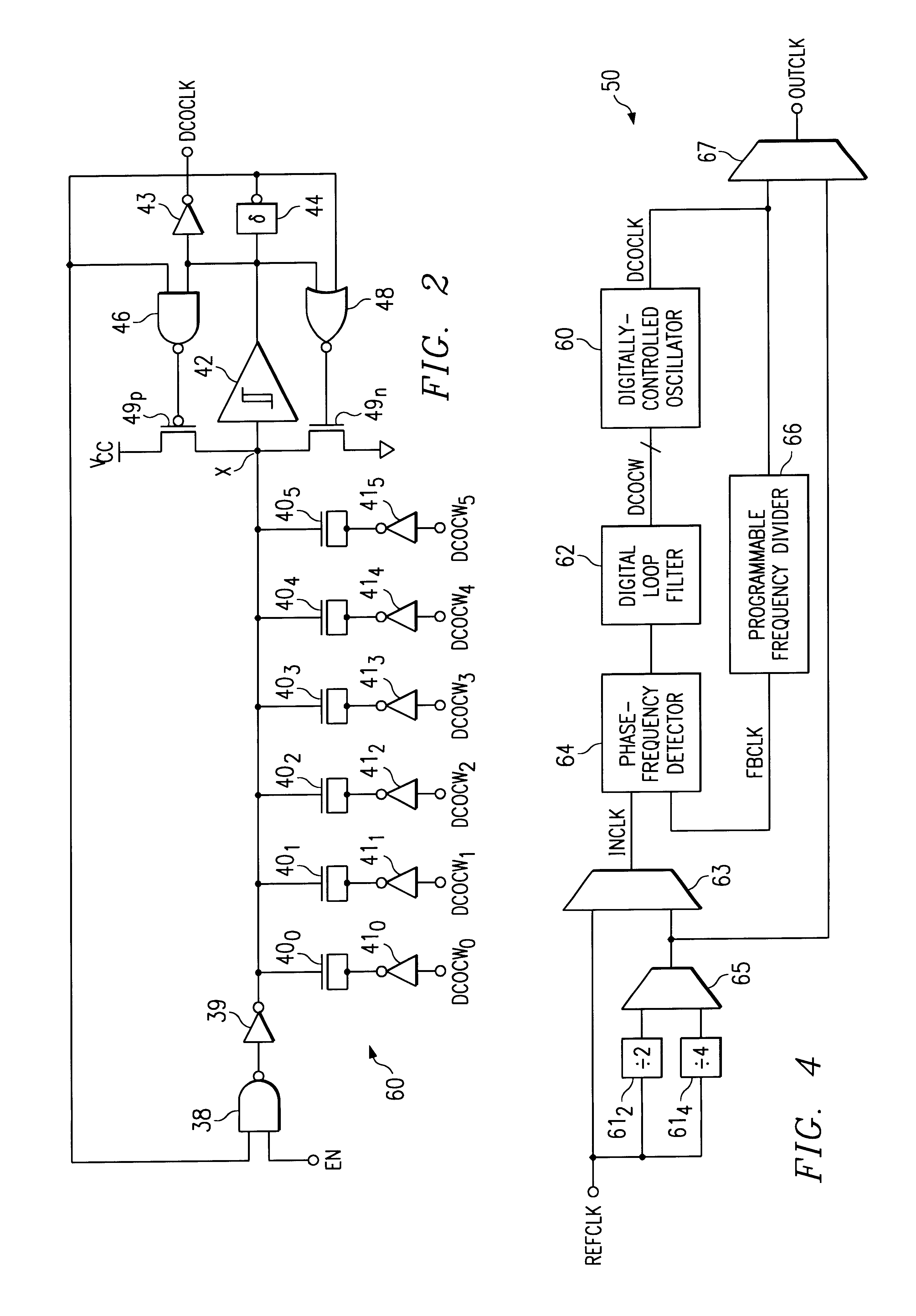
[0033]The construction and operation of digitally-controlled oscillator (DCO) 60 according to the preferred embodiment of the present invention will now be described in detail. As will become apparent from the following description, many integrated circuit applications may benefit from the present invention, in that the DCO may be efficiently realized in a modest amount of chip area for a given resolution. Integrated circuits which are to operate at high frequencies while still concerned with power dissipation (and thus operating at low power supply voltages), may also particularly benefit from the present invention. According to the preferred embodiment of the invention, DCO 60 synthesizes a periodic signal on output line DCOCLK at a frequency that is determined by the value of a digital control word on lines DCOCW, in a beneficial manner, as will now be described in detail relative to FIG. 2.

[0034]FIG. 2 illustrates the construction of DCO 60 according to the preferred embodiment ...


PUM


Abstract

A digitally-controlled oscillator (DCO) (60), such as may be used in clock generator or clock recovery circuitry in an integrated circuit, is disclosed. The disclosed DCO (60) is a single-stage oscillator including a variable load implemented as a binary-weighted array of switched capacitors (40). Each of capacitors (40) has a plate connected to a common node (X), and a plate that receives a signal corresponding to one bit of a digital control word (DCOCW). The common capacitor node (X) is also connected to the input of a Schmitt trigger (42) that produces the output clock signal (OUTCLK) and a feedback signal that is applied to logic (38, 39) that inverts the common node of the capacitors (40). The switching time at the input of Schmitt trigger (42) depends upon the variable load presented by the array of switched capacitors (40), which is controlled by the digital control word (DCOCW). As a result, the clock signal (OUTCLK) is digitally synthesized by a single stage of the DCO (60). A digital phase-locked loop (PLL) clock generator circuit (50) including a phase detector (64), digital loop filter (62) in combination with the DCO (60), and a programmable frequency divider (66) providing a feedback path from the output of the DCO (60) to the phase detector (64), is also disclosed. The PLL clock generator (50) may be used in an integrated circuit such as a digital signal processor (30) or microprocessor, and is particularly well-suited for use in a battery-powered portable electronic system (200).

Description

CROSS-REFERENCE TO RELATED APPLICATIONS[0001]This application is a continuation of Ser. No. 08 / 960,920 filed Oct. 30, 1997 now U.S. Pat. No. 6,028,488 which claims the benefit, under 35 U.S.C. §119(e)(1), of U.S. Provisional Application No. 60 / 030,723, filed Nov. 8, 1996, and of U.S. Provisional Application No. 60 / 036,865, filed Feb. 5, 1997, both incorporated herein by this reference.STATEMENT REGARDING FEDERALLY SPONSORED RESEARCH OR DEVELOPMENT[0002]Not applicable.BACKGROUND OF THE INVENTION[0003]This invention is in the field of integrated circuits, and is more specifically directed to oscillator circuits, such as may be used in clock generation and clock recovery in very large scale integrated (VLSI) logic circuits such as microprocessors and digital signal processors.[0004]As is fundamental in the art, the operating clock rates of modern VLSI circuits, such as microprocessors and digital signal processors (DSPs), have increased greatly over recent years. These clock rates, now...

Claims


Application Information

Patent Timeline
IPC IPC(8): H03L7/093H03K3/00H03L7/099H03K3/03H03L7/08H03L7/183H03L7/16H03B5/08H03B5/12
CPCH03K3/03H03L7/183H03L7/0991H03L7/093H03J2200/10
Inventor LANDMAN, PAUL E.LEE, WAIFATTARUSO, JOHN W.DE WIT, MICHAEL
Owner TEXAS INSTR INC
Why Eureka
Try Eureka