

Magnetic core including magnet for magnetic bias and inductor component using the same
a magnetic core and magnetic bias technology, applied in the field of magnetic cores, can solve the problems of increasing increasing the number of inductor components, and increasing the number of inductances, so as to reduce the thickness of the magnet for magnetic bias, prevent degradation of the characteristics of the inductor component, and improve the effect of magnetic bias strength
- Summary
- Abstract
- Description
- Claims
- Application Information
AI Technical Summary
Benefits of technology
Problems solved by technology
Method used
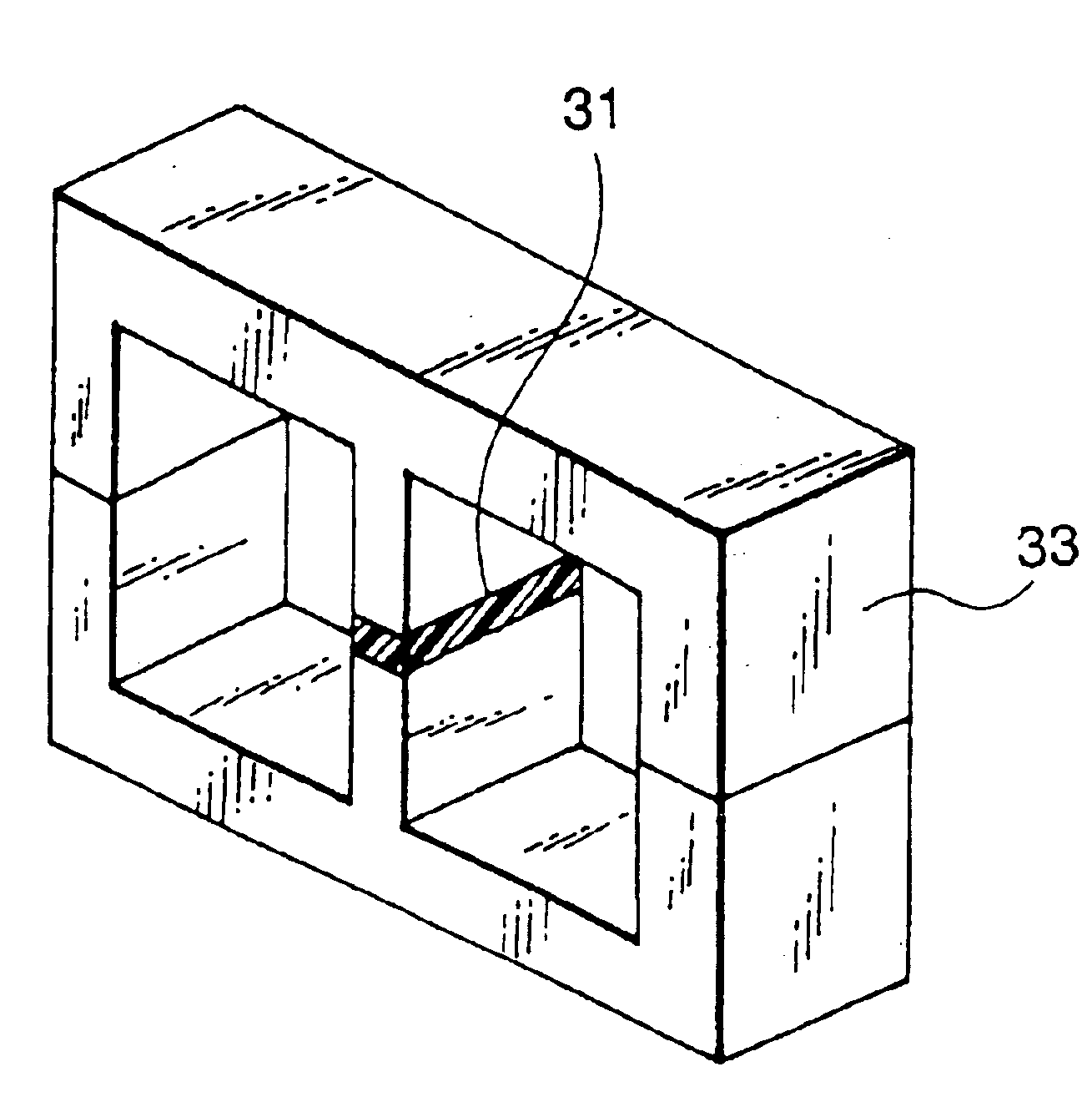
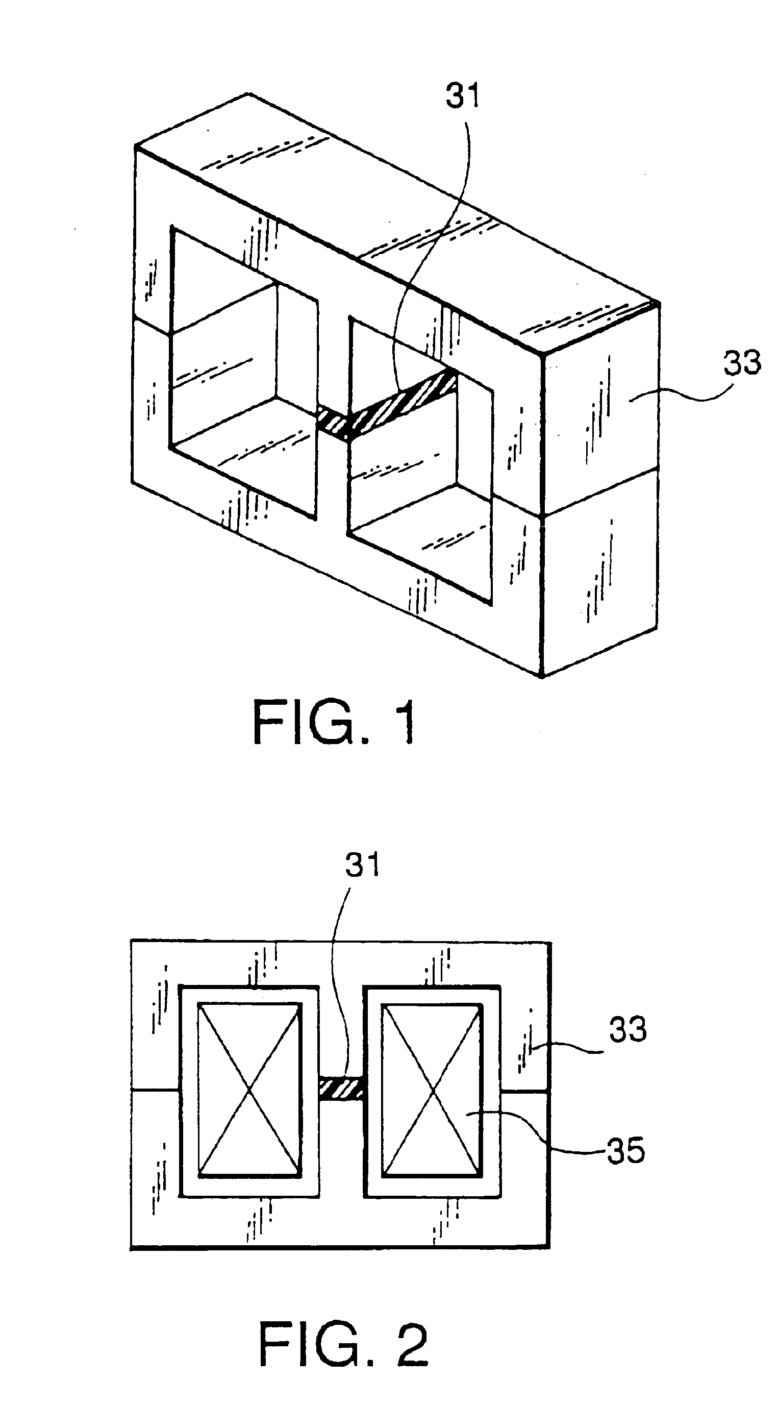
Image

Examples
example 1
[0070]Six kinds of glass powders were prepared. These were ZnO—B2O3—PbO (1) having a softening point of about 350° C., ZnO—B2O3—PbO (2) having a softening point of about 400° C., B2O3—PbO having a softening point of about 450° C., K2O—SiO2—PbO having a softening point of about 500° C., SiO2—B2O3—PbO (1) having a softening point of about 550° C., and SiO2—B2O3—PbO (2) having a softening point of about 600° C. Each powder had a particle diameter of about 3 μm.
[0071]A Sm2Co17 magnet powder was produced as the magnet powder from a sintered material by pulverization. That is, a Sm2Co17 sintered material was produced by a common powder metallurgy process. Regarding the magnetic characteristics of the resulting sintered material, the (BH)max was 28 MGOe, and the coercive force was 25 KOe. This sintered material was roughly pulverized with a jaw crusher, disk mill, etc., and thereafter, was pulverized with a ball mill so as to have an average particle diameter of about 5.0 μm.
[0072]Each of ...
example 2
[0080]A magnet powder and a glass powder were mixed in order that each of the resulting mixtures had a glass powder content of 0.1%, 0.5%, 1.0%, 2.5%, 5.0%, 7.5%, 10%, or 12.5% by weight. The magnet powder was the Sm2Co17 magnet powder used in Example 1, and the glass powder was a SiO2—B2O3—PbO glass powder of about 3 μm having a softening point of about 500° C. Each of the resulting mixtures was heat-treated at 550° C. in Ar and, therefore, the magnet powder was coated with glass. The magnet powder coated with glass was mixed with 50% by volume of polyimide resin as a binder, and the resulting mixture was made into a sheet by a doctor blade method. The resulting sheet was dried to remove the solvent, and thereafter, was molded by hot press to have a thickness of 0.5 mm.
[0081]The magnetic characteristics of this bonded magnet were measured using a separately prepared test piece in a manner similar to that in Example 1. As a result, each of the bonded magnets exhibited an intrinsic c...
example 3
[0101]Six kinds of glass powders were prepared. These were ZnO—B2O3—PbO (1) having a softening point of about 350° C., ZnO—B2O3—PbO (2) having a softening point of about 400° C., B2O3—PbO having a softening point of about 450° C., K2O—SiO2—PbO having a softening point of about 500° C., SiO2—B2O3—PbO (1) having a softening point of about 550° C., and SiO2—B2O3—PbO (2) having a softening point of about 600° C. Each powder had a particle diameter of about 3 μm.
[0102]Regarding the preparation of a Sm2Co17 magnet powder, an ingot was pulverized and sintered by a common powder metallurgy process so as to produce a sintered material. The resulting sintered material was finely pulverized into 2.3 μm. The magnetic characteristic of the resulting magnet powder was measured with VSM, and as a result, the coercive force iHc was about 9 KOe.
[0103]Each of the resulting magnet powders was mixed with the respective glass powders at a content of 1%., Each of the resulting mixtures was heat-treated i...
PUM
| Property | Measurement | Unit |
|---|---|---|
| gap length | aaaaa | aaaaa |
| resistivity | aaaaa | aaaaa |
| particle diameter | aaaaa | aaaaa |
Abstract
Description
Claims
Application Information