Spin-valve type magnetoresistive sensor and method of manufacturing the same

a magnetoresistive sensor and spin-valve technology, applied in the field of spin-valve type magnetoresistive sensor, can solve the problems of difficult to precisely define the track width, difficulty in narrowing the track width to be adapted, and the risk of causing the problem, so as to achieve high reliability and reliable magnetoresistive effect, superior durability, heat resistance and corrosion resistan

Inactive Publication Date: 2005-07-05
TDK CORPARATION
View PDF16 Cites 5 Cited by
  • Summary
  • Abstract
  • Description
  • Claims
  • Application Information

AI Technical Summary

Benefits of technology

[0118]With the above feature, a highly reliable magnetoresistive head can be obtained which is superior in durability, heat resistance and corrosion resistance, and which can generate an exchange anisotropic magnetic field at a sufficient level.

Problems solved by technology

The conventional spin-valve type magnetoresistive sensor shown in FIG. 13 however has a risk of causing the problem described below.
Also, due to variations in widths of the opposite dead areas, it is difficult to precisely define the track width.
This results in a problem of difficulty in narrowing the track width to be adapted for a higher recording density.
However, the spin-valve type magnetoresistive sensor shown in FIG. 14 has a problem of corrosion because the antiferromagnetic layer 22 is formed of a Ni—Mn alloy.
This has necessarily raised such a drawback that the bias layers 26, 26 are poor in heat resistance and corrosion resistance.
Accordingly, the magnetization direction of the pinned magnetic layer 23 and the magnetization direction of the free magnetic layer 25 are out of the orthogonal relation, thus resulting in a problem that an output signal waveform has poor symmetry.
However, when the spin-valve type magnetoresistive sensor shown in FIG. 14 is provided in a magnetic recording device or the like, the sensor is subjected to a high temperature over 100° C. due to a temperature rise in the device and Joule heat produced by a detection electric current.
As a result, a problem of causing the Barkhausen noise has occurred.
Another problem is that, because the Fe—Mn alloy is poorer in corrosion resistance than the Ni—Mn alloy, the bias layers are corroded by, e.g., a weak alkaline solution, containing sodium tripolyphosphate or the like, and an emulsifier which are used in manufacturing steps of the magnetoresistive head, and hence the exchange anisotropic magnetic field is reduced.
In addition, corrosion of the bias layers further proceeds in the magnetic recording device, whereby durability of the device deteriorates.
This results in a problem of increasing the number of manufacturing steps.
Further, the necessity of cleaning the surface of the uppermost layer by ion milling or reverse sputtering raises another problem attributable to the cleaning, such as an adverse effect upon generation of the exchange anisotropic magnetic field caused by contamination with foreign matters deposited again on the surface or disorder of the crystal state at the surface.
This may accompany a risk of lowering stability of a reproduced waveform at both ends of the track width Tw and hence causing a problem such as a servo error.
In the spin-valve type magnetoresistive sensor MR3 constructed as shown in FIG. 18, therefore, there has been a risk of lowering stability of a reproduced waveform at both ends of the track width Tw and hence causing a problem such as a servo error.
This invites the occurrence of Barkhausen noise or the like and deteriorates magnetic stability.

Method used


Image

  • Spin-valve type magnetoresistive sensor and method of manufacturing the same
  • Spin-valve type magnetoresistive sensor and method of manufacturing the same
  • Spin-valve type magnetoresistive sensor and method of manufacturing the same

Examples


first embodiment

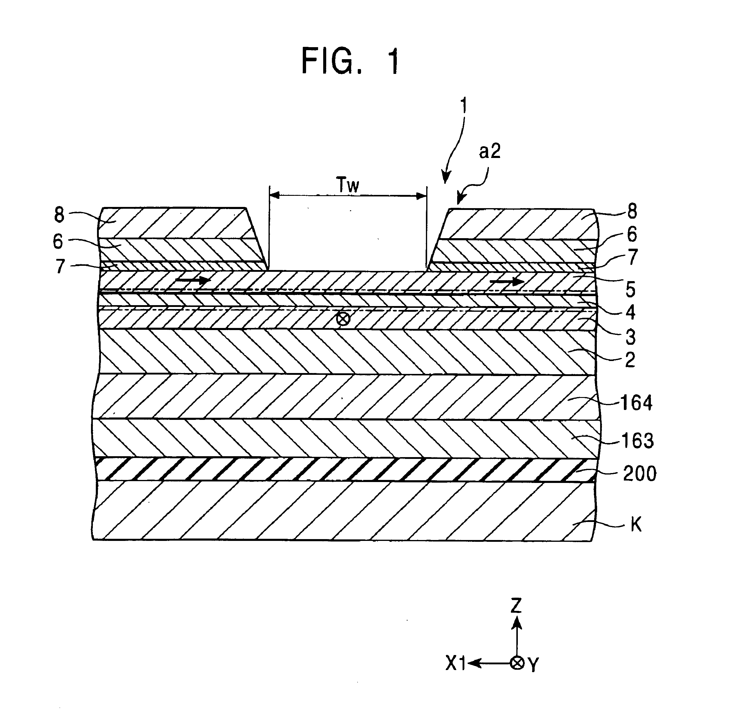
[0147]FIG. 1 is a sectional view showing the structure of a spin-valve type magnetoresistive sensor according to a first embodiment of the present invention, as viewed from the side facing a recording medium. FIGS. 5 and 6 are each a perspective view showing a magnetoresistive head including the spin-valve type magnetoresistive sensor according to the first embodiment.

[0148]Above and below the spin-valve type magnetoresistive sensor of the present invention, shielding layers are formed with gap layers interposed therebetween. The spin-valve type magnetoresistive sensor, the gap layers, and the shielding layers cooperatively construct a GMR head h1 for reproduction.

[0149]An inductive head h2 for recording may be layered on the GMR head h1 for reproduction.

[0150]As shown in FIG. 5, the GMR head h1 including the spin-valve type magnetoresistive sensor is provided on a trailing end face 151d of a slider 151 along with the inductive head h2, whereby a magnetoresistive head 150 is constru...

second embodiment

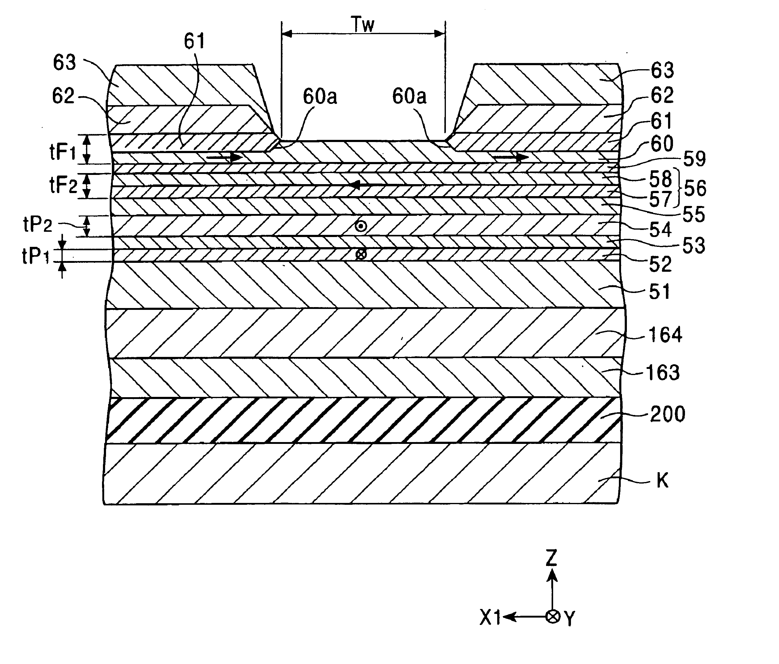
[0313]FIG. 7 is a cross-sectional view schematically showing a spin-valve type magnetoresistive sensor according to a second embodiment of the present invention, and FIG. 8 is a sectional view showing the structure of the spin-valve type magnetoresistive sensor shown in FIG. 7, as viewed from the side facing a recording medium.

[0314]Similarly to the spin-valve type magnetoresistive sensor shown in FIG. 1, the spin-valve type magnetoresistive sensor of this embodiment is also provided, for example, on a trailing end face of a floating slider mounted in a hard disk device, and is used to detect a magnetic field recorded on a hard disk or the like.

[0315]In FIGS. 7 and 8, a Z-direction represents the moving direction of a magnetic recording medium such as a hard disk, and a Y-direction represents the direction of a leakage magnetic field from the magnetic recording medium.

[0316]The spin-valve type magnetoresistive sensor shown in FIGS. 7 and 8 is one of the so-called bottom type single-...

third embodiment

[0350]FIG. 9 is a cross-sectional view schematically showing a spin-valve type magnetoresistive sensor according to a third embodiment of the present invention, and FIG. 10 is a sectional view showing the structure of the spin-valve type magnetoresistive sensor shown in FIG. 9, as viewed from the side facing a recording medium.

[0351]Similarly to the spin-valve type magnetoresistive sensors described above, the spin-valve type magnetoresistive sensor of this embodiment is also provided, for example, on a trailing end face of a floating slider mounted in a hard disk device, and is used to detect a magnetic field recorded on a hard disk or the like.

[0352]In FIGS. 9 and 10, a Z-direction represents the moving direction of a magnetic recording medium such as a hard disk, and a Y-direction represents the direction of a leakage magnetic field from the magnetic recording medium.

[0353]Also in the spin-valve type magnetoresistive sensor of this embodiment, a magnetization direction of a free ...


PUM

PropertyMeasurementUnit
temperatureaaaaaaaaaa

Abstract

A spin-valve type magnetoresistive sensor with a bias structure enabling a magnetization direction of a free magnetic layer to be uniformly arranged with certainty. The spin-valve type magnetoresistive sensor comprises an antiferromagnetic layer; a pinned magnetic layer having a magnetization direction made stationary; a nonmagnetic electrically conductive layer formed between the pinned magnetic layer and a free magnetic layer; soft magnetic layers that are arranged on the free magnetic layer while a spacing corresponding to a track width is left between the soft magnetic layers and that fill recesses in the free magnetic layer on both sides of an area corresponding to the track width; bias layers formed on the soft magnetic layers; and electrically conductive layers. The antiferromagnetic layer and the bias layers are each made of an alloy containing at least one or more elements selected from among Pt, Pd, Rh, Ru, Ir, Os, Au, Ag, Cr, Ni, Ne, Ar, Xe and Kr, as well as Mn.

Description

BACKGROUND OF THE INVENTION[0001]1. Field of the Invention[0002]The present invention relates to a spin-valve type magnetoresistive sensor wherein electrical resistance is changed depending on the relationship between a stationary magnetization direction of a pinned magnetic layer and a magnetization direction of a free magnetic layer which is affected by an external magnetic field. More particularly, the present invention relates to a spin-valve type magnetoresistive sensor having superior heat resistance, a magnetoresistive head incorporating the spin-valve type magnetoresistive sensor, and to a method of manufacturing the spin-valve type magnetoresistive sensor, by which the magnetization direction of the free magnetic layer and the magnetization direction of the pinned magnetic layer can be easily set in orthogonal relation.[0003]2. Description of the Related Art[0004]There are known two types of magnetic heads utilizing a magnetoresistive effect; i.e., an AMR (Anisotropic Magne...

Claims


Application Information

Patent Timeline
Patent Type & Authority Patents(United States)
IPC IPC(8): G11B5/39G01R33/09H01F10/32
CPCB82Y25/00G01R33/093G11B5/3903H01F10/3277Y10T428/12861Y10T428/12389Y10T428/24479Y10T428/12951Y10T428/2495Y10T428/12465
Inventor HASEGAWA, NAOYA
Owner TDK CORPARATION
Why Eureka
Try Eureka