Illuminating device

a technology of illumination device and dielectric barrier, which is applied in the direction of fixed installation, light and heating apparatus, sustainable buildings, etc., can solve the problems of high cost of inverter, ozone generation, and dielectric barrier discharge lamp enclosed, so as to prevent local high temperature rise and facilitate assembly

Inactive Publication Date: 2005-07-05
HARISON TOSHIBA LIGHTING CORP
View PDF2 Cites 15 Cited by
  • Summary
  • Abstract
  • Description
  • Claims
  • Application Information

AI Technical Summary

Benefits of technology

[0021]With the illuminating device according to the present invention, the assembling is easy including the connection of a plurality of dielectric barrier discharge lamps

Problems solved by technology

Therefore, the inverters of as many as the number of the lamps are necessary, which results in high cost for inverters.
However, such dielectric barrier discharge lamp enclosed with mercury had the following problems.
When the discharge lamp is lighted by an inverter which provides a sine wave voltage having a frequency of 50 KHz at its output terminals with one end of the output terminal being grounded, a corona is discharged from the outer electrode of the lamp connected with the high voltage output terminal of the inverter due to the high lamp voltage exceeding 2000 Vrms and the corona result in generation of ozone.
Further, when such dielectric barrier discharge lamp enclosed with mercury is driven by a square wave voltage, which is used for lighting a diele

Method used


Image

  • Illuminating device
  • Illuminating device
  • Illuminating device

Examples


first embodiment

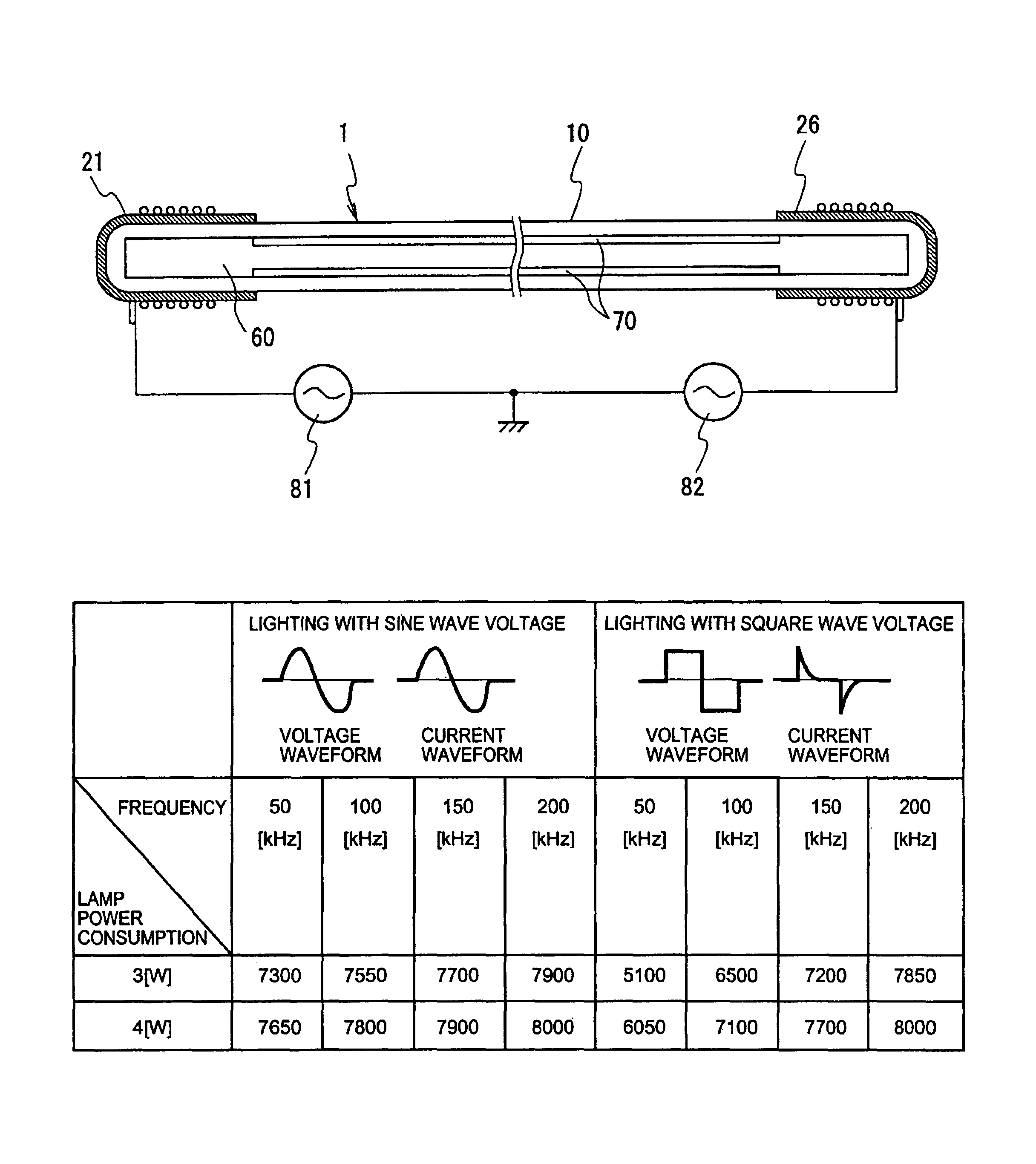
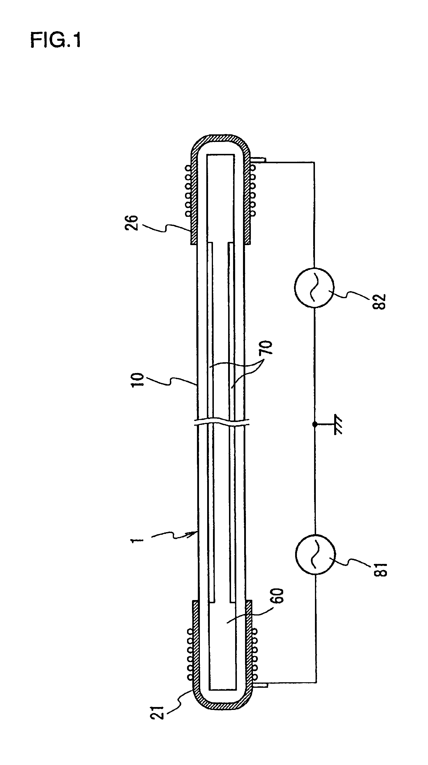
[0029]FIG. 1 shows a construction of the illuminating device according to the present invention. A dielectric barrier discharge lamp 1 is composed of a tubular glass lamp vessel 10 on the inner wall of which a phosphor layer 70 is formed and mercury and rare gas 60 are enclosed inside. Outer electrodes 21, 22 made of an electrically conductive layer are provided circumferentially on an outer surface of both ends of the glass lamp vessel 10. Specific structure of the dielectric barrier discharge lamp 1 is as follows.

[0030]Material: Borosilicate Glass[0031]Dimension: outer diameter; 2.6 mm, inner diameter; 2.0 mm, total length; 397 mm

[0032]Material: aluminum foil+electrically conductive silicone adhesive layer,[0033]Length: 17 mm

[0034]Material: 3-wavelength phosphor.[0035]Thickness: 20 μm

[0036]Enclosed gas: mixed gas of neon and argon (composition ratio: neon / argon=90 mol % / 10 mol %).[0037]Pressure: 8 kPa.[0038]Mercury: charged amount 3 mg.

[0039]A first and second high frequency power...

second embodiment

[0058]Next, FIG. 5 is an exploded perspective view of an illuminating device, which is the present invention. The illuminating device is a back light illuminating device, which lights a plurality of dielectric barrier discharge lamp 1 all at once and illuminates a liquid crystal panel from rear side. That is, this device includes twelve dielectric barrier discharge lamps 1 (hereinafter called EEFL) which are arranged in parallel, a side plate 101 for holding each ends of these EEFL 1, and a couple of relay boards 102 which connect each outer electrodes of EEFL 1. The device further includes an inverter 86, which is a high frequency power source, a harness 103, which supplies high frequency voltage to the both relay boards 102 from the inverter 86, lower frames 104, which fix the both side plates 101 and relay boards at a prescribed position, a reflecting plate 105, which reflects lights from a number of EEFL 1 to a prescribed direction, a diffusion plate 106 diffusion sheets 107, 10...

third embodiment

[0066]Next, the back light illumination device according to the present invention is explained with reference to FIG. 6.

[0067]Compared with the illumination device shown in FIG. 5, the third embodiment is characterized in that the electrode portion for power supply is changed and an electrode made of electrically conductive silicone rubber 111 and a side plate 112 for supporting 111 are used instead of the side plate 101 and the relay board 102 of the back light unit of FIG. 5. That is, the back light illumination device includes a plurality of dielectric barrier discharge lamps (EEFL) 1 arranged in parallel, electrically conductive silicone rubber electrode 111, a side plate 112 for supporting and reinforcing the electrode 111, and an inverter 86 for supplying high frequency sine wave voltage.

[0068]More specifically, the back light illumination device further includes a couple of electrically conductive silicone rubber electrodes 111 which are arranged on the both sides of a plural...


PUM


Abstract

An illuminating device according to an embodiment of the present invention includes a dielectric barrier discharge type low pressure discharge lamp 1 composed of a tubular glass lamp vessel 10, in which mercury and rare gas are enclosed, a first and a second electrode 21,26, which are made of electrically conductive layer, are provided on an outer surface of both ends of the tubular glass lamp vessel 10 and a high frequency power source of a floating output type 81,82, which supplies a sine wave voltage between the first and the second electrodes of the dielectric barrier discharge type low pressure discharge lamp 1 having a neutral point of the sine wave voltage being grounded, and which supplies a frequency in a range from 40 kHz to 100 kHz.

Description

[0001]The present application claims the benefit of priority of Japan Application No. 2002-370768 filed Dec. 20, 2002 which is incorporated by reference.BACKGROUND TECHNOLOGY OF THE INVENTION[0002]The present invention relates to an illuminating device suited for back light units used for high luminance liquid crystal display device.[0003]As a back light source used for liquid crystal monitor for a personal computer or a liquid crystal TV set that requires high luminance and high efficiency, a cold cathode low pressure discharge lamp is generally used. The cold cathode low-pressure discharge lamp encloses mercury and rare gas as a discharge medium inside a tubular glass lamp vessel. A phosphor layer is formed on the inner wall of the glass lamp vessel, and the cold cathodes are provided in the glass vessel at its both ends. A high frequency sine wave voltage is supplied between the cold cathodes provided by a high frequency power source to light the low-pressure discharge lamp.[0004...

Claims


Application Information

Patent Timeline
IPC IPC(8): H05B41/28H05B41/24H05B41/26
CPCH05B41/24H05B41/2806Y02B20/22Y02B20/00H05B41/26
Inventor TAKEDA, YUJITAKAGI, MASAMINAKANO, HIROKIKURITA, TAKAYOSHIHIRAO, TOMOMASA
Owner HARISON TOSHIBA LIGHTING CORP
Why Eureka
Try Eureka