Power conversion device

a power conversion device and power conversion technology, applied in the direction of electric variable regulation, process and machine control, instruments, etc., can solve the problems of high power loss, low switching speed of igbt, and difficulty in operating igbt at a high frequency, so as to achieve low forward voltage drop, high frequency operation, and high efficiency

Inactive Publication Date: 2005-07-05
ORIGIN CO LTD
View PDF5 Cites 12 Cited by
  • Summary
  • Abstract
  • Description
  • Claims
  • Application Information

AI Technical Summary

Benefits of technology

[0008]The present invention can be applied to power conversion for the commercial AC power supply high voltage of an AC 400V system by using semiconductor switching devices, in particular FETs, having low withstand voltages. Specifically, in the present invention, two input capacitors are connected in series across an input DC power supply voltage, two inverters constituted by FETs having low withstand voltages are respectively connected between both ends of the input capacitors, and control signals supplied to the inverters are modulated so that each of the voltages applied to the inverters is approximately half of the input DC power supply voltage. As a result, the voltages across the input capacitors balance with each other, and it becomes possible to employ semiconductor switching devices such as FETs having withstand voltages lower than the input DC power supply voltage.
[0013]In the first or second aspect of the present invention, frequency modulation control of the inverter circuits to balance the voltages across the first and second input capacitors may be performed such that the frequency of a frequency modulated signal supplied to an inverter circuit in which the voltage across an input capacitor provided therein is higher is increased and the frequency of a frequency modulated signal supplied to another inverter circuit in which the voltage across another input capacitor provided therein is lower is decreased.
[0017]According to the present invention, it is possible to configure a power conversion device by using semiconductor switching devices such as FETs which are inexpensive and have low forward voltage drops and withstand voltages lower than the maximum value of a DC voltage including the fluctuation thereof obtained by rectifying a commercial AC power supply high voltage of a 400V system and so forth, thereby realizing high frequency operation, high efficiency, and reduction in cost.

Problems solved by technology

However, FETs having high withstand voltages generally have high on-resistance values and bring about high power loss.
In contrast, IGBTs having high withstand voltages and being capable of supplying high current are readily available, but such type of IGBT has low switching speed and it is hard to operate the IGBT at a high frequency.
As a result, the size of a power conversion device becomes large and it becomes difficult to reduce the voltages of ripples.

Method used


Image

  • Power conversion device
  • Power conversion device
  • Power conversion device

Examples


Embodiment Construction

[0024]Hereinbelow, embodiments of the present invention will be described with reference to the attached drawings.

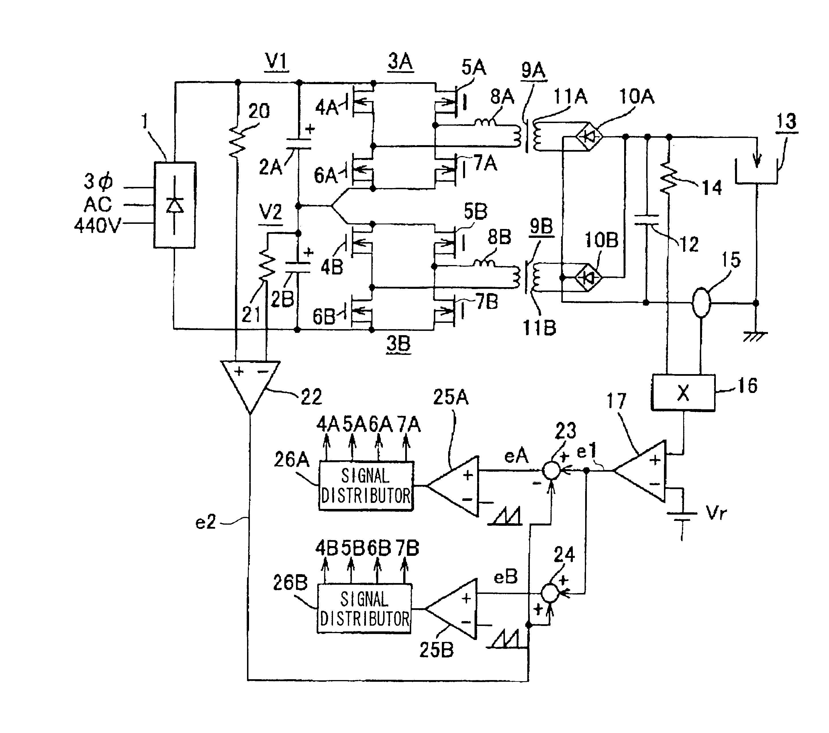
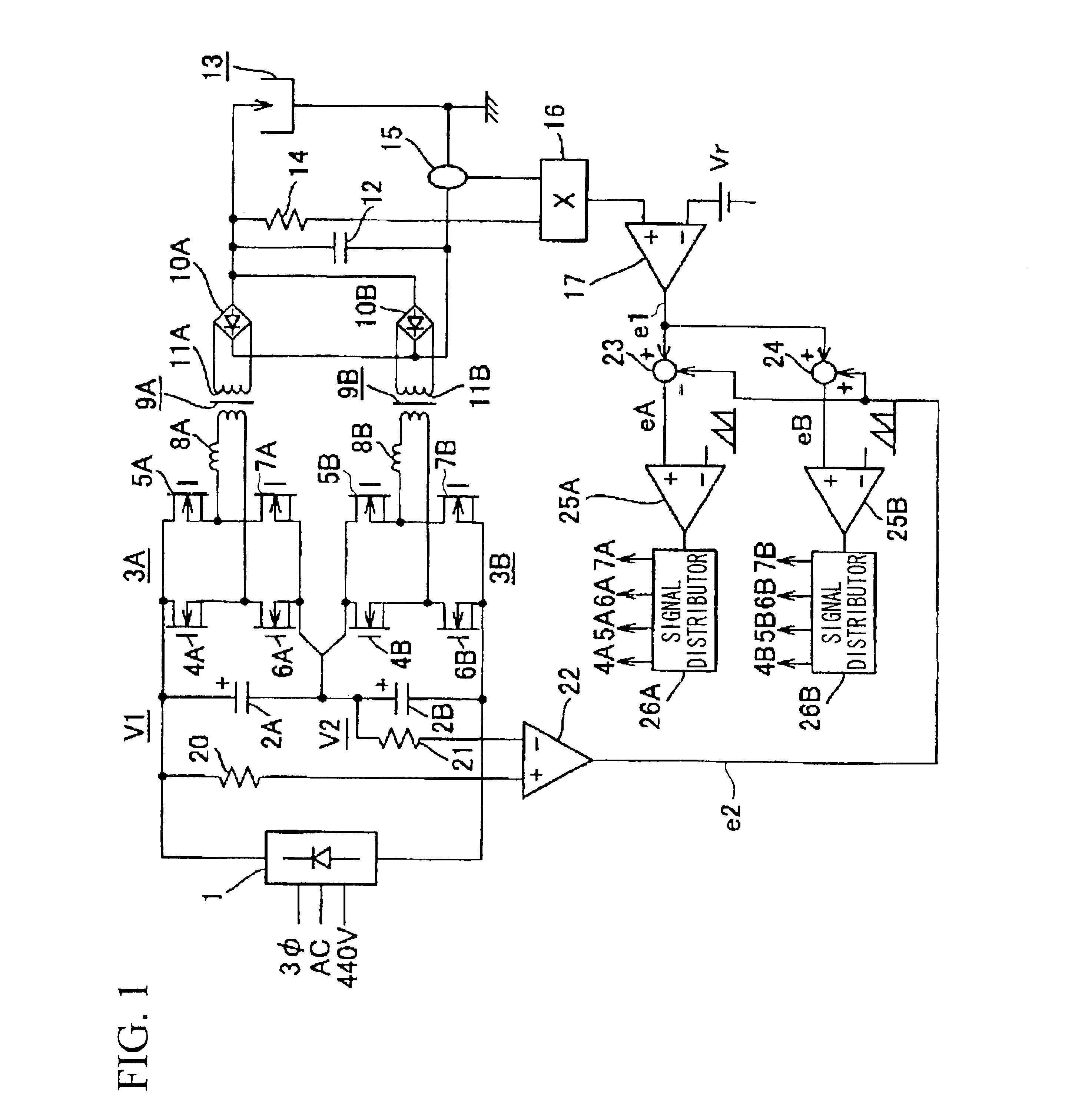
[0025]FIG. 1 shows a circuit of a sputtering power supply device, which is a power conversion device according to a first embodiment of the present invention. Reference symbol 1 denotes a three-phase rectifier which rectifies a commercial AC power supply high voltage being a three-phase AC 400V. The maximum value of the rectified voltage reaches 620V including the fluctuation of the input commercial AC power supply high voltage. Since the withstand voltage of a typical electrolytic capacitor used for smoothing the rectified voltage is about 450V, electrolytic capacitors (input capacitors) 2A and 2B having the withstand voltage of 400V are employed here, and these input capacitors are connected in series. Hereinbelow, the circuit connected to the input capacitor 2A is referred to as an A-system circuit, and the circuit connected to the input capacitor 2B is referred to as...


PUM


Abstract

A low cost power conversion device operating at a high frequency with high efficiency is realized by using semiconductor switching devices such as FETs being inexpensive and having low withstand voltages and low forward voltage drops. A second error signal obtained by comparing the voltages across two input capacitors connected between both ends of a DC input power supply is subtracted / added from / to a first error signal obtained from a voltage corresponding to a combined DC output of rectifying circuits and the voltage corresponding to a predetermined reference power. Based on the resultant signals, the voltage of a control signal supplied to an inverter circuit in which the voltage across an input capacitor is higher is increased, while the voltage of a control signal supplied to another inverter circuit in which the voltage across another input capacitor is lower is decreased, thereby balancing the voltages across the input capacitors.

Description

BACKGROUND OF THE INVENTION[0001]1. Field of the Invention[0002]The present invention relates to a power conversion device such as a sputtering power supply device used in a DC (direct current) sputtering apparatus, and in particular relates to a power conversion device which is suitable for performing power conversion for a commercial AC (alternating current) high voltage power supply system which generates a voltage within the range of AC 400V to 480V.[0003]2. Description of the Related Art[0004]A DC sputtering apparatus introduces inert gas such as argon gas into a vacuum chamber, applies a negative polarity voltage of several hundred volts to a target electrode, and causes plasma discharge to positively ionize the inert gas. Such a DC sputtering apparatus is used as a thin film deposition apparatus which accelerates positive ions and strikes the accelerated positive ions on a target surface to evaporate a target material, and which deposits vapor of the target material on a surf...

Claims


Application Information

Patent Timeline
Patent Type & Authority Patents(United States)
IPC IPC(8): H02M3/28H02M3/24
CPCH02M3/285H02M2001/0022H02M2001/0074H02M1/0022H02M1/0074
Inventor WATANABE, KIYOMITOMAKI, TERUO
Owner ORIGIN CO LTD
Why Eureka
Try Eureka