Metal gas separation membrane

a metal gas and separation membrane technology, applied in the field of metal gas separation membranes, can solve the problems of low porosity, low porosity of membranes, and low stability of membranes, and achieve the effects of low porosity, high hydrogen selectivity, and low porosity

Inactive Publication Date: 2005-07-12
SIEMENS ENERGY INC
View PDF45 Cites 29 Cited by
  • Summary
  • Abstract
  • Description
  • Claims
  • Application Information

AI Technical Summary

Benefits of technology

[0015]In view of the foregoing, an improved metal gas separation membrane for separating hydrogen from a gas steam includes a quantity of metal particles in the form of fibers and/or powders that are compacted together and bonded with one another to form a porous body that is selectively permeable to hydrogen. The porous body may be of a constant porosity throughout or may have a porosity that is “graded,” i.e., increases from a first surface to a secon

Problems solved by technology

Polymeric membranes and membrane modules for hydrogen separation suffer from a lack of high selectivity toward hydrogen over other gases, which results in a relatively impure product gas.
Such membranes also suffer from a lack of stability at operating temperatures above 480° F.
All are fabricated with a narrow pore size distribution, with the porous inorganic membranes exhibiting high hydrogen permeability but low selectivity due to relatively large mean pore diameters.
Such materials are brittle and thus susceptible to failure due to cracking, and the sealing and fixturing of such porous inorganic-based membranes limit their use to relatively low temperature applications.
Potential leak paths between the feed and permeate gas streams can exist due to differences in the

Method used


Image

  • Metal gas separation membrane
  • Metal gas separation membrane
  • Metal gas separation membrane

Examples


first embodiment

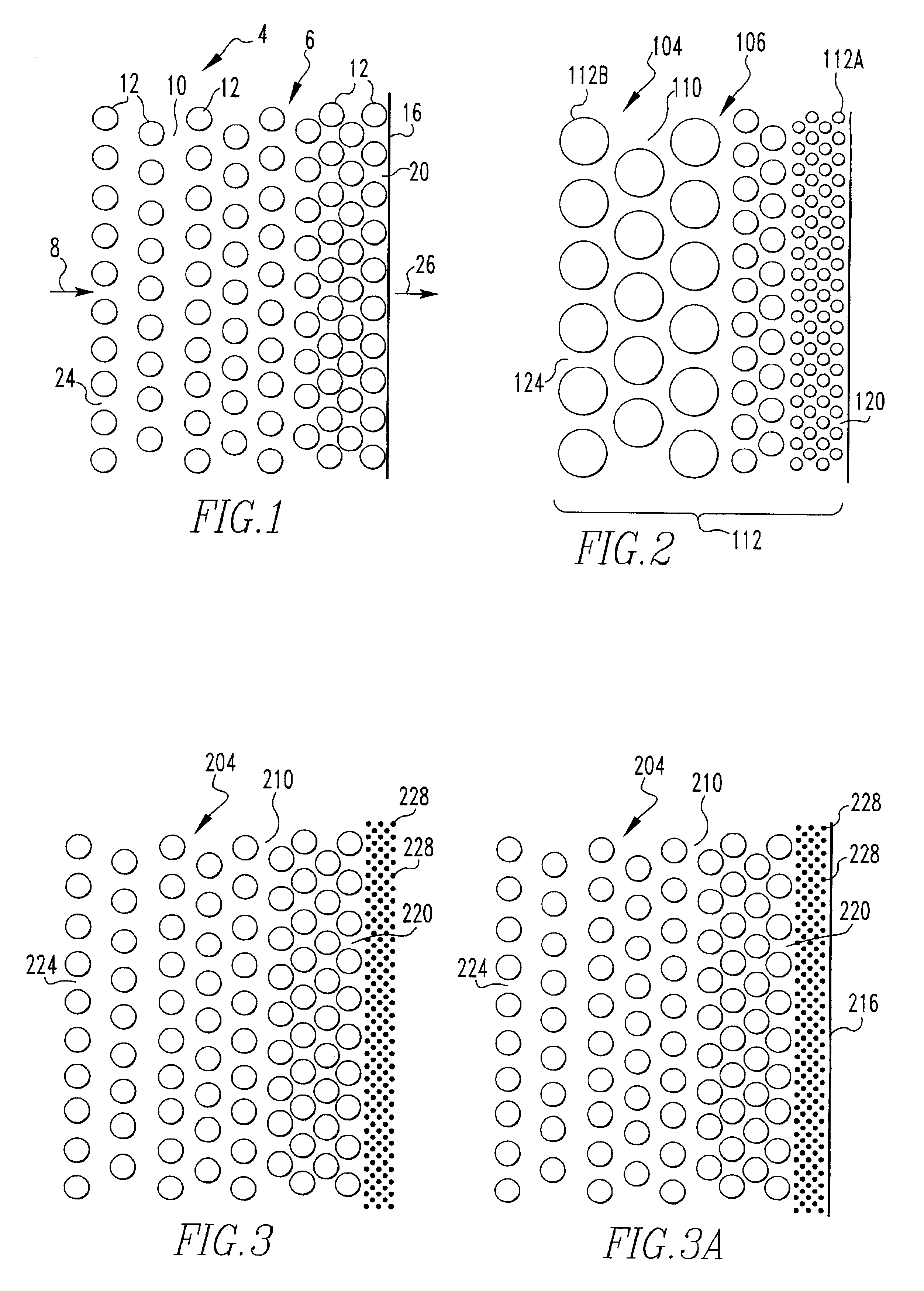
[0051]a metal gas separation membrane 4 in accordance with the present invention is indicated generally in FIG. 1. The metal gas separation membrane 4 is advantageously configured to separate hydrogen gas from a gas stream 8. As will be set forth more fully below, the metal gas separation membrane 4 is also advantageously configured to be highly selective to hydrogen, meaning that it permits the permeation of hydrogen therethrough and resists the permeation of other gases. The metal gas separation membrane 4 further advantageously permits relatively high flow rates of hydrogen therethrough.

[0052]The metal gas separation membrane 4 includes a transmission member 6 that can be of numerous shapes, such as plates, tubes, honeycomb configurations, and other such shapes. The transmission member 6 is depicted schematically in cross-section FIG. 1, and it includes a porous body 10 made out of a plurality of metal particles 12 compressed and bonded together and a metal coating 16 on the poro...

second embodiment

[0067]a metal gas separation membrane 104 in accordance with the present invention is indicated generally in FIG. 2. The metal gas separation membrane 104 is similar to the metal gas separation membrane 4 except that the metal gas separation membrane 104 includes a transmission member 106 having a porous body 110 in which the graded porosity thereof is achieved in a different fashion than that of the porous body 10. More specifically, the metal particles 112 of the porous body 110 vary in size from relatively finer metal particles 112A at the first surface 120 to relatively coarser metal particles 112B at the second surface 124.

[0068]By way of example, the relatively finer metal particles 112A may be in the form of fibers of a size in the range of about 25 to 100 nanometers in diameter and 112B may be in the form of fibers of a size in the range of about <1 to 50 microns in diameter and <10 millimeters in length. Particles of other sizes and shapes may, however, be used without depa...

third embodiment

[0070]a metal gas separation membrane 204 in accordance with the present invention is indicated generally in FIG. 3. The metal gas separation membrane 204 is similar to the metal gas separation membrane 4, except that the metal gas separation membrane 204 includes a layer of ceramic particles 228 instead of employing the metal coating 16. The ceramic particles 228 are either of a physically smaller size than any of the metal particles of the porous body 210, or the ceramic particles 228 are compacted to a greater degree than any of the metal particles such that the layer of ceramic particles 228 has an even lower porosity than any other region of the porous body 210. The layer of ceramic particles 228 thus defines the first surface 220 of the porous body 210, with the porosity at the first surface 220 being less than the porosity at the second surface 224 of the porous body 210.

[0071]The layer of ceramic particles 228 thus advantageously provides high hydrogen selectivity in the por...


PUM

PropertyMeasurementUnit
Concentrationaaaaaaaaaa
Sizeaaaaaaaaaa
Permeabilityaaaaaaaaaa

Abstract

An improved metal gas separation membrane for separating hydrogen from a gas steam includes a quantity of metal particles that are bonded together to form a porous body that is selectively permeable to hydrogen. The porous body may have a porosity that increases from a first surface to an opposite second surface. The metal gas separation membrane may additionally include a coating of ceramic particles on the first surface thereof to further decrease the porosity at the first surface. Alternatively, or in addition thereto, the metal gas separation membrane may include a thin foil or coating of a dense precious metal such as palladium, palladium-alloys, and the like applied thereto that is permeable by hydrogen according to a chemisorption-dissociation-diffusion transport phenomenon. Still alternatively, or in addition thereto, the porous body may include a catalytic enhancement that can interact with a gas stream to increase the concentration of hydrogen according to various catalytic reactions such as the water gas shift reaction and the ammonia decomposition reaction.

Description

BACKGROUND OF THE INVENTION[0001]1. Field of the Invention[0002]The present invention relates generally to gas separation membranes and, more particularly, to a metal membrane for the separation of hydrogen gas from a gas stream.[0003]2. Description of the Related Art[0004]Membranes and membrane modules for the separation of hydrogen from other gases are generally known. In particular, useful membranes for hydrogen separation typically can be categorized as being of four general types: (i) polymeric, (ii) porous inorganic, (iii) self-supporting non-porous metal, and (iv) non-porous metal supported on a porous rigid matrix such as metal or ceramic.[0005]Polymeric membranes are commonly used in the form of extended flat sheets of small diameter hollow fibers. Flat sheet polymeric membranes are most often incorporated into spiral-wound modules. Hollow fiber membranes are incorporated into hollow-fiber modules which are very similar in design to shell-and-tube heat exchangers.[0006]Poly...

Claims


Application Information

Patent Timeline
IPC IPC(8): B01D53/22B01D71/02B01D71/00C01B3/04C01B3/00C01B3/50C01B3/16B01J23/40B01J35/06B01J35/00
CPCB01D53/22B01D53/228B01D67/0069B01D67/0072B01D69/02B01D71/02B01D71/022B01D71/024C01B3/047C01B3/16C01B3/503C01B3/505B01J23/40B01J35/065C01B2203/0283Y02E60/364B01D2325/02B01D2325/10Y02E60/36Y02P20/52
Inventor ALVIN, MARY ANNE
Owner SIEMENS ENERGY INC
Why Eureka
Try Eureka