Method and device for treating surfaces using a glow discharge plasma

a technology of glow discharge and surface treatment, which is applied in the direction of chemical vapor deposition coating, electrical equipment, coatings, etc., can solve the problems of unsuitable surface treatment, high cost, and high pressure used, and achieve the effect of simple method and device, reduced disadvantage of direct plasma exposur

Inactive Publication Date: 2005-07-19
TETRA LAVAL HLDG & FINANCE SA
View PDF9 Cites 45 Cited by
  • Summary
  • Abstract
  • Description
  • Claims
  • Application Information

AI Technical Summary

Benefits of technology

[0013]It is an object of the invention to create a method and a device for surface treatment using a one atmosphere glow discharge plasma that will reduce the disadvantage of direct plasma exposure as used according to the state of the art (exposure between the electrodes) without the complications of remote exposure as used according to the state of the art. Method and device according to the invention are to be suitable in particular for treating a surface of thin plastic film material, in particular for coating such film material, which is in the form of a web, with a barrier layer. The method and device according to the invention are to be simple and are to allow high quality treatment, particularly treatment without the negative effects of plasma filaments.
[0020]Experiments show that positioning a surface to be treated as described above in the edge region of the plasma space (fringing field) reduces damage caused by plasma filaments drastically and still allows treating speeds (e.g. deposition rates) that are in the same order of magnitude as for plasma exposure between the electrodes.
[0021]When coating a thin plastic film with a barrier layer of, for example, silicon oxide, silicon nitride, silicone carbide, or carbon (amorphous or crystalline) according to the inventive method the coated film material has a constant and high barrier quality. The constancy of the barrier quality is thought to be due to the absence of plasma filaments in the edge region of the plasma space in which the surface to be treated is exposed to the plasma. Due to the absence of plasma filaments, damage to the substrate and the coating is prevented and deposition is highly regular.

Problems solved by technology

However, as the pressures used are very low, devices suitable for such surface treatment need to be vacuum tight and are correspondingly complicated and costly, particularly if large surfaces such as, for instance, webs of film are to be handled or if large amounts of items are to be handled with relatively short cycle times (without venting of a plasma chamber in each treatment cycle).
Plasma sustained in air of ambient pressure is used for producing ozone For this process it does not matter that such one atmosphere plasmas are highly filamentary which, however, renders them unsuitable for surface treatment, in particular for treatment of sensitive surfaces.
However, it shows that the uniformity of such one atmosphere plasmas is very sensitive to small parameter changes (power, frequency, gas composition, gas pressure, geometry etc.) such that it is hardly possible to sustain such a plasma in a continuously working system over a longer period of time strictly without filaments.
“it becomes difficult to prevent occasional plasma filaments from developing at the edges of the workpiece, the electrode edges, or the edges of the web when a workpiece is directly exposed to the plasma”, i.e. when the workpiece is positioned between the two plate electrodes.
Such occasional filaments become particularly troublesome in the above-named barrier coating application in which each filament punches a hole into the plastic film resulting in a hole in the produced barrier coating also and, therefore, resulting in a leak which, even if microscopically small, outweighs the effect of the barrier layer over a large area of the coated surface.
Therefore, it seems hardly possible to achieve top quality barrier properties in a direct plasma treatment using a one atmosphere plasma.
However, this again renders a device for carrying out the process more complicated and restricts the availability of some of the reactive particles, in particular the availability of very short lived particles.

Method used


Image

  • Method and device for treating surfaces using a glow discharge plasma
  • Method and device for treating surfaces using a glow discharge plasma
  • Method and device for treating surfaces using a glow discharge plasma

Examples


Embodiment Construction

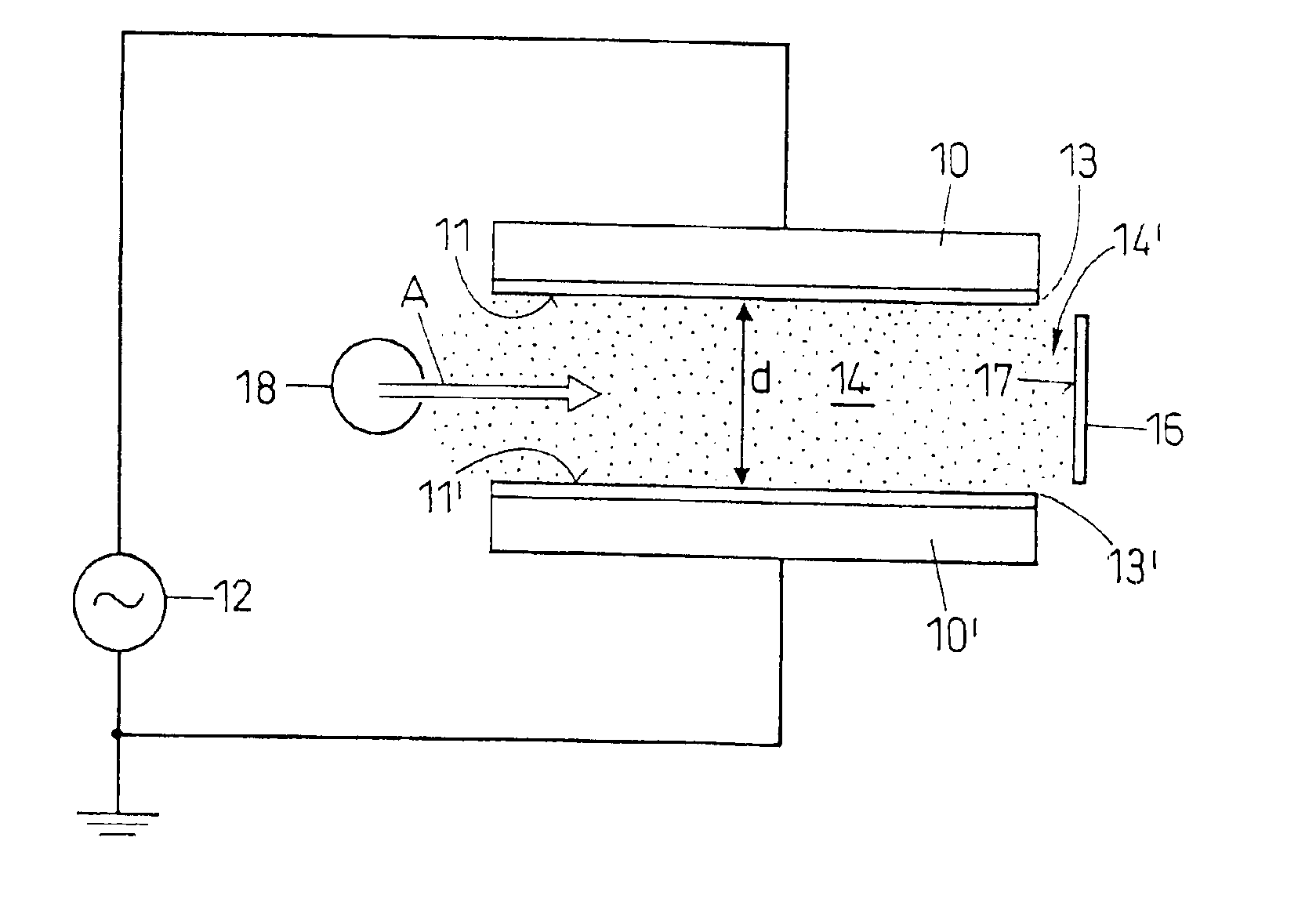
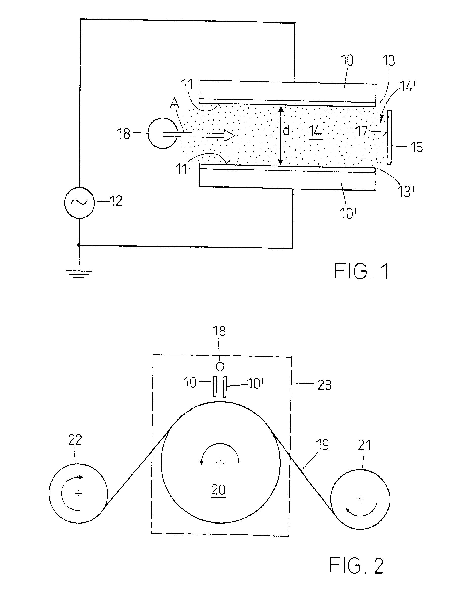
[0028]FIG. 1 shows the principle of the inventive method. Between two plate electrodes 10 and 10′ with two electrode faces 11 and 11′ being arranged substantially parallel to each other at a distance d between each other a plasma is lighted and sustained by energizing the electrodes with per se known suitable energizing means 12 comprising, for example, a power supply, high voltage transformer, and matching network. The electrode faces 11 and 11′ have aligned edges, in particular one pair of such aligned edges 13 and 13′. The aligned edges 13, 13′of the two electrode faces 11, 11′ define a plasma space 14 between them. whereby the plasma sustained between the two electrode faces 11 and 11′ visibly protrudes over pairs of aligned edges 13 and 13′ of the electrode faces in edge regions 14′ (fringing field).

[0029]The device further comprises means 18 for feeding a treatment gas or treatment gas mixture to the plasma space 14, 14′ and means for positioning a substrate 16 with a surface ...


PUM

PropertyMeasurementUnit
pressureaaaaaaaaaa
pressureaaaaaaaaaa
distanceaaaaaaaaaa

Abstract

In a process for treating a surface with the aid of a glow discharge plasma sustained in a gas of substantially ambient pressure between two electrodes (10, 10′) unwanted effects of plasma filaments occurring in such a plasma are prevented by positioning the surface (17) to be treated in an edge region (14′) of the plasma. The surface is placed on one side of a plasma space (14) defined by the electrode faces (11, 11′) beyond a pair of aligned edges (13, 13′) of the electrode faces (11, 11′), at a distance of a few millimeters from these edges (13, 13′), and facing these edges (13, 13′). The treatment gas or treatment gas mixture is fed to the plasma space (14) from a second side opposite the edge region (14′) in which the surface (17) to be treated is positioned. During treatment, a substrate (16) whose one surface (17) is to be treated is either stationary or is advanced in a direction substantially perpendicular to the electrode faces (11, 11′).

Description

BACKGROUND OF THE INVENTION[0001]1. Field of the Invention[0002]The present invention is directed toward a method and a device for treating surfaces with reactive particles generated in a glow discharge plasma, in particular for treating surfaces that are highly sensitive to thermal loading. The plasma used in the inventive method and device is a so-called one atmosphere glow discharge plasma, i.e. a plasma sustained in a gas at pressures in the range of ambient pressure (ca. 0.5 to 1.5 bar or 50,000 to 150,000 Pa).[0003]2. Description of Related Art[0004]Glow discharge plasmas are sustained in a gas, for example with the aid of an alternating electric field of a suitable voltage and frequency by which the gas is partially ionized to contain ions and electrons in addition to neutral atoms, molecules and radicals. The glow discharge plasma is usually sustained between two plate electrodes being correspondingly energized and having two substantially parallel electrode faces between wh...

Claims


Application Information

Patent Timeline
Patent Type & Authority Patents(United States)
IPC IPC(8): C23C16/50C23C16/503H01J37/32H05H1/24B01J19/08C08J7/00C08J7/06C23C16/505
CPCC23C16/503H01J37/32018H01J37/32532
Inventor SCHWARZENBACH, WALTERROESSLER, BERTRANDFAYET, PIERRE
Owner TETRA LAVAL HLDG & FINANCE SA
Why Eureka
Try Eureka