
Component with repaired thermal barrier coating

a technology of thermal barrier coating and components, which is applied in the direction of superimposed coating process, liquid/solution decomposition chemical coating, machines/engines, etc., can solve the problems of high temperature durability of engine components that must correspondingly increase, and are susceptible to damage, so as to achieve the effect of increasing the strength of the repair coating

Inactive Publication Date: 2005-07-19
GENERAL ELECTRIC CO
View PDF4 Cites 14 Cited by
  • Summary
  • Abstract
  • Description
  • Claims
  • Application Information

AI Technical Summary

Benefits of technology

[0008]The present invention provides a method of repairing a thermal barrier coating on a component that has suffered localized spallation of the thermal barrier coating. After cleaning the surface area of the component exposed by the localized spallation, a ceramic paste comprising a ceramic powder in a binder is applied to the surface area of the component. The binder is then reacted to yield a ceramic-containing repair coating that covers the surface area of the component and comprises the ceramic powder in a matrix of a material formed when the binder was reacted. The binder is preferably a ceramic precursor material that can be converted immediately to a ceramic or allowed to thermally decompose over time to form a ceramic, such that the repair coating has a ceramic matrix. According to the invention, each step of the repair method can be performed while the component remains installed, e.g., in a gas turbine engine. Immediately after the reaction step, the gas turbine engine can resume operation to further react / convert the binder, by which the strength of the repair coating increases.
[0009]In view of the above, it can be appreciated that the invention overcomes several disadvantages of prior methods used to repair thermal barrier coatings. In particular, the method of this invention does not require the thermal barrier coating to be completely removed, nor does the invention require removal of the component in order to repair its thermal barrier coating. As a further advantage, the repair process does not require a high temperature treatment, since the repair coating exhibits sufficient strength to withstand engine operation, during which time the precursor binder is gradually converted to form a ceramic matrix. As a result, minimal downtime is necessary to complete the repair and resume operation of the turbine engine. In the case of large power generation turbines, the cost is avoided of completely halting power generation for an extended period in order to remove, repair and then reinstall a component that has suffered only localized spallation. Also avoided is the need to decide whether or not to continue operation of the turbine until the spalled component is no longer salvageable at the risk of damaging the turbine.

Problems solved by technology

However, as operating temperatures increase, the high temperature durability of the components of the engine must correspondingly increase.
Nonetheless, when used to form components of the turbine, combustor and augmentor sections of a gas turbine engine, such alloys alone are often susceptible to damage by oxidation and hot corrosion attack and may not retain adequate mechanical properties.
The latter requirement is particularly demanding due to the different coefficients of thermal expansion between ceramic topcoat materials and the superalloy substrates they protect.
The service life of a TBC system is typically limited by a spallation event brought on by thermal fatigue.
Accordingly, a significant challenge of TBC systems has been to obtain a more adherent ceramic layer that is less susceptible to spalling when subjected to thermal cycling.
Though significant advances have been made, there is the inevitable requirement to repair components whose thermal barrier coatings have spalled.
However, grit blasting is a slow, labor-intensive process and erodes the surface beneath the coating.
With repetitive use, the grit blasting process eventually destroys the component.
The use of an alkaline solution to remove a thermal barrier coating is also less than ideal, since the process requires the use of an autoclave operating at high temperatures and pressures.
Consequently, conventional repair methods are labor-intensive and expensive, and can be difficult to perform on components with complex geometries, such as airfoils and shrouds.
In the case of large power generation turbines, completely halting power generation for an extended period in order to remove components whose TBC's have suffered only localized spallation is not economically desirable.
As a result, components identified as having spalled TBC are often analyzed to determine whether the spallation has occurred in a high stress area, and a judgment is then made as to the risk of damage to the turbine due to the reduced thermal protection of the component, which if excessive can lead to catastrophic failure of the component.
If the decision is to continue operation, the spalled component must typically be scrapped at the end of operation because of the thermal damage inflicted while operating the component without complete TBC coverage.

Method used


Image

  • Component with repaired thermal barrier coating
  • Component with repaired thermal barrier coating

Examples


Embodiment Construction

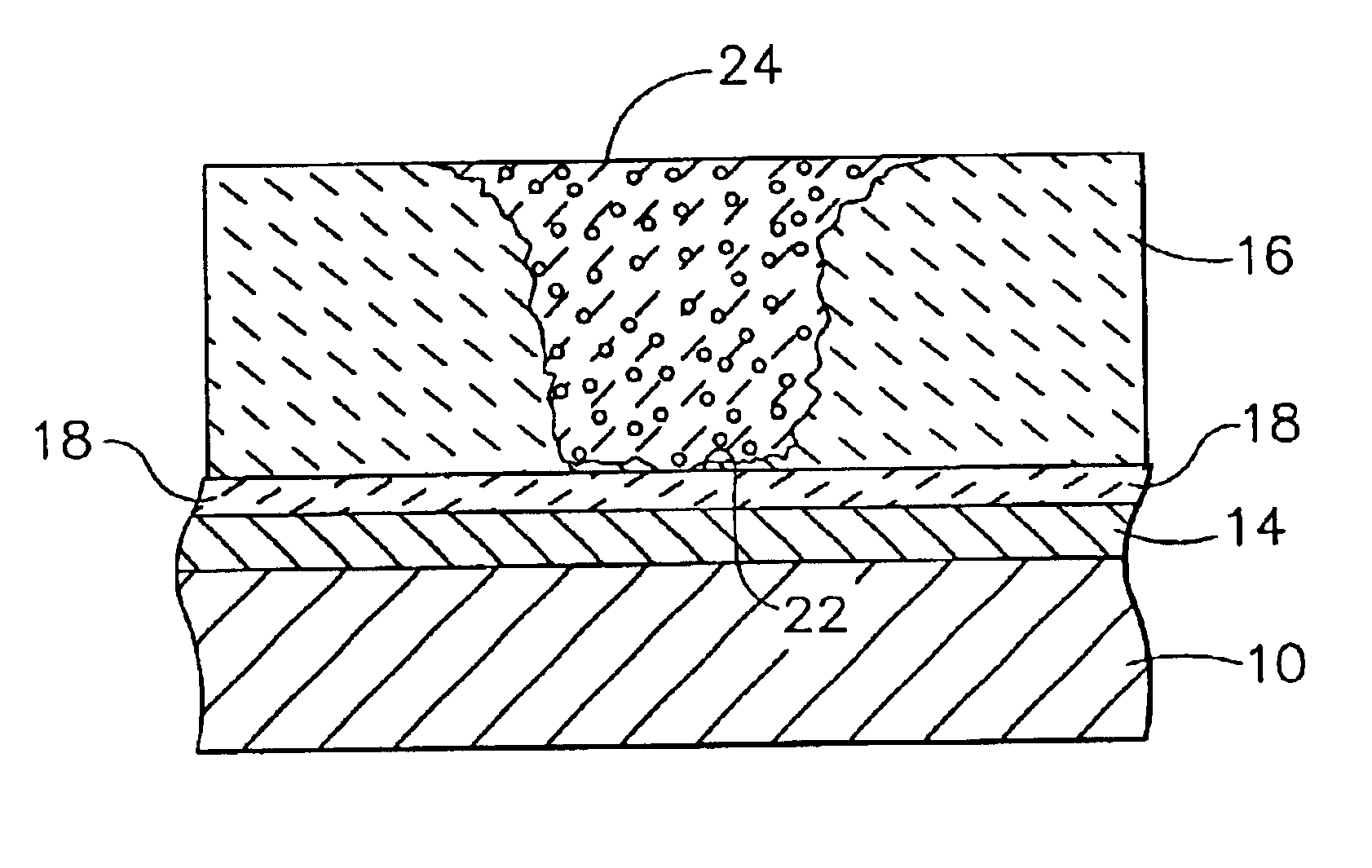
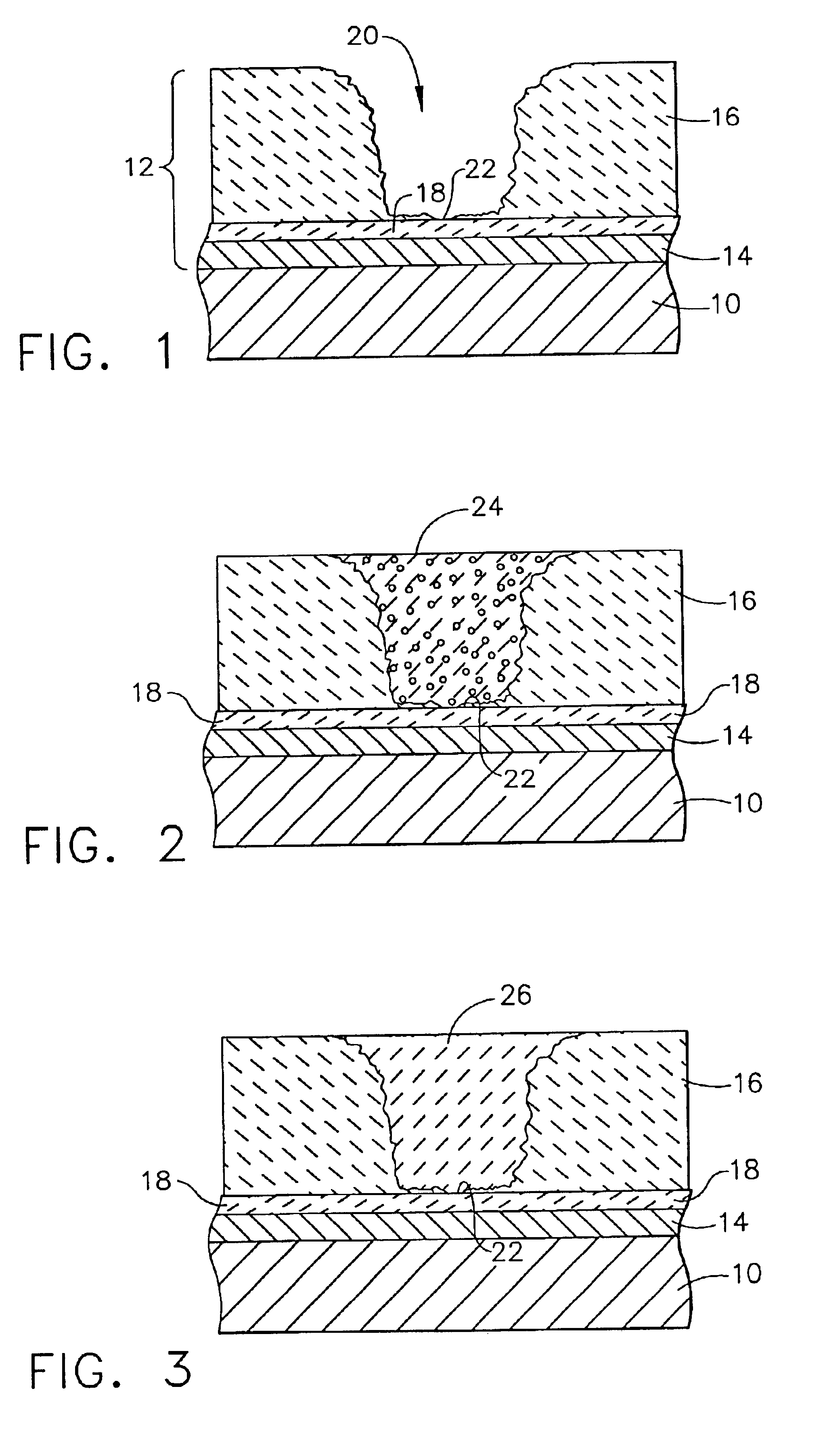
[0013]The present invention is directed to components protected by thermal barrier coatings for operation within environments characterized by relatively high temperatures, and therefore subjected to severe thermal stresses and thermal cycling. Notable examples of such components include the high and low pressure turbine nozzles and blades, shrouds, combustor liners and augmentor hardware of gas turbine engines for use in aircraft and industrial applications. While the advantages of this invention are particularly applicable to components of gas turbine engines, the invention is generally applicable to any component in which a thermal barrier coating is used to thermally insulate a component from its environment.

[0014]Represented in FIG. 1 is a surface region of a component 10 protected by a thermal barrier coating (TBC) system 12. The TBC system 12 is shown as being composed of a bond coat 14 formed on the surface of the component 10, and a ceramic layer 16 deposited on the bond co...


PUM

PropertyMeasurementUnit
Percent by massaaaaaaaaaa

Abstract

A method of repairing a thermal barrier coating (16) on a component (10) designed for use in a hostile thermal environment, such as turbine, combustor and augmentor components of a gas turbine engine. The method more particularly involves repairing a thermal barrier coating (16) on a component (10) that has suffered localized spallation (20) of the thermal barrier coating (16). After cleaning the surface area (22) of the component (10) exposed by the localized spallation (20), a ceramic paste (24) comprising a ceramic powder in a binder is applied to the surface area (22) of the component (10). The binder is then reacted to yield a ceramic-containing repair coating (26) that covers the surface area of the component and comprises the ceramic powder in a matrix of a material formed when the binder was reacted. The binder is preferably a ceramic precursor material that can be converted immediately to a ceramic or allowed to thermally decompose over time to form a ceramic, such that the repair coating (26) has a ceramic matrix. The repair method can be performed while the component (10) remains installed, e.g., in a gas turbine engine. Immediately after the reaction step, the gas turbine engine can resume operation during which the binder is further reacted / converted and the strength of the repair coating increases.

Description

[0001]This is a division of application Ser. No. 09 / 687,721, filed Oct. 12, 2000, now U.S. Pat. No. 6,413,578.FIELD OF THE INVENTION[0002]This invention relates to thermal barrier coatings for components exposed to high temperatures, such as the hostile thermal environment of a gas turbine engine. More particularly, this invention is directed to a method for repairing a thermal barrier coating that has suffered localized spallation.BACKGROUND OF THE INVENTION[0003]Higher operating temperatures for gas turbine engines are continuously sought in order to increase their efficiency. However, as operating temperatures increase, the high temperature durability of the components of the engine must correspondingly increase. Significant advances in high temperature capabilities have been achieved through the formulation of nickel and cobalt-base superalloys. Nonetheless, when used to form components of the turbine, combustor and augmentor sections of a gas turbine engine, such alloys alone a...

Claims


Application Information

Patent Timeline
IPC IPC(8): C23C24/08C23C28/00C23C24/00C23C4/10F01D5/28C23C4/11C23C18/06C23C18/12C23C26/00F02C7/00
CPCC23C24/08C23C28/00Y02T50/67Y10T428/25Y10T428/24521Y10T428/20Y10T428/252Y10T428/24479Y02T50/60
Inventor STOWELL, WILLIAM R.JOHNSON, ROBERT A.SKOOG, ANDREW J.BEGOVICH, JOSEPH THOMASRENTZ, THOMAS WALTERMURPHY, JANE ANNLEE, CHING-PANGIVKOVICH, JR., DAINEL P.
Owner GENERAL ELECTRIC CO
Learn More