Carbonyl-stress improving agent and peritoneal dialysate

a carbonyl-stress and dialysate technology, applied in the field of peritoneal dialysate, can solve the problems of peritoneal fusion, lower water removal ability, abdominal protein denaturation and hardening, etc., and achieve the effect of reducing damage from carbonyl compounds, improving carbonyl-stress state, and minimizing as much as possible damage from these carbonyl compounds

Inactive Publication Date: 2005-07-19
MIYATA TOSHIO +3
View PDF98 Cites 26 Cited by
  • Summary
  • Abstract
  • Description
  • Claims
  • Application Information

AI Technical Summary

Benefits of technology

[0013]An objective of the present invention is to provide a method for reducing damage from carbonyl compounds during peritoneal dialysis, specifically for improving the carbonyl-stress state, as well as to provide a dialysate and pharmaceutical agent required for this method. The “carbonyl compound” in the present invention means a carbonyl compound derived from patients undergoing peritoneal-dialysis, a carbonyl compound generated in the peritoneal dialysate during manufacturing or storing, and a carbonyl compound generated in the peritoneal cavity during peritoneal dialysis. The present invention aims to minimize as much as possible the damages from these carbonyl compounds on the patients undergoing dialysis.

Problems solved by technology

However, it is known that long-term treatment with peritoneal dialysis can progressively lower the ability of water removal, and can result in abdominal protein denaturation and hardening, peritoneal fusion, and such abnormalities.
Glucose is unstable to heat, and a part thereof is degraded during heat sterilization.
However, such acidic buffers carry risks such as suppressing immunological defense mechanisms of peritoneal macrophages, causing the onset of peritonitis due to bacterial infection, and being cytotoxic to peritoneal mesothelial cells.
On the other hand, a peritoneal dialysate formulated with a high concentration of glucose can modify proteins, and therefore, such dialysates are unfavorable for the peritoneum.
Renal failure often accompanies conditions having an overload of carbonyl compounds (carbonyl stress).

Method used


Image

  • Carbonyl-stress improving agent and peritoneal dialysate
  • Carbonyl-stress improving agent and peritoneal dialysate
  • Carbonyl-stress improving agent and peritoneal dialysate

Examples


example 1

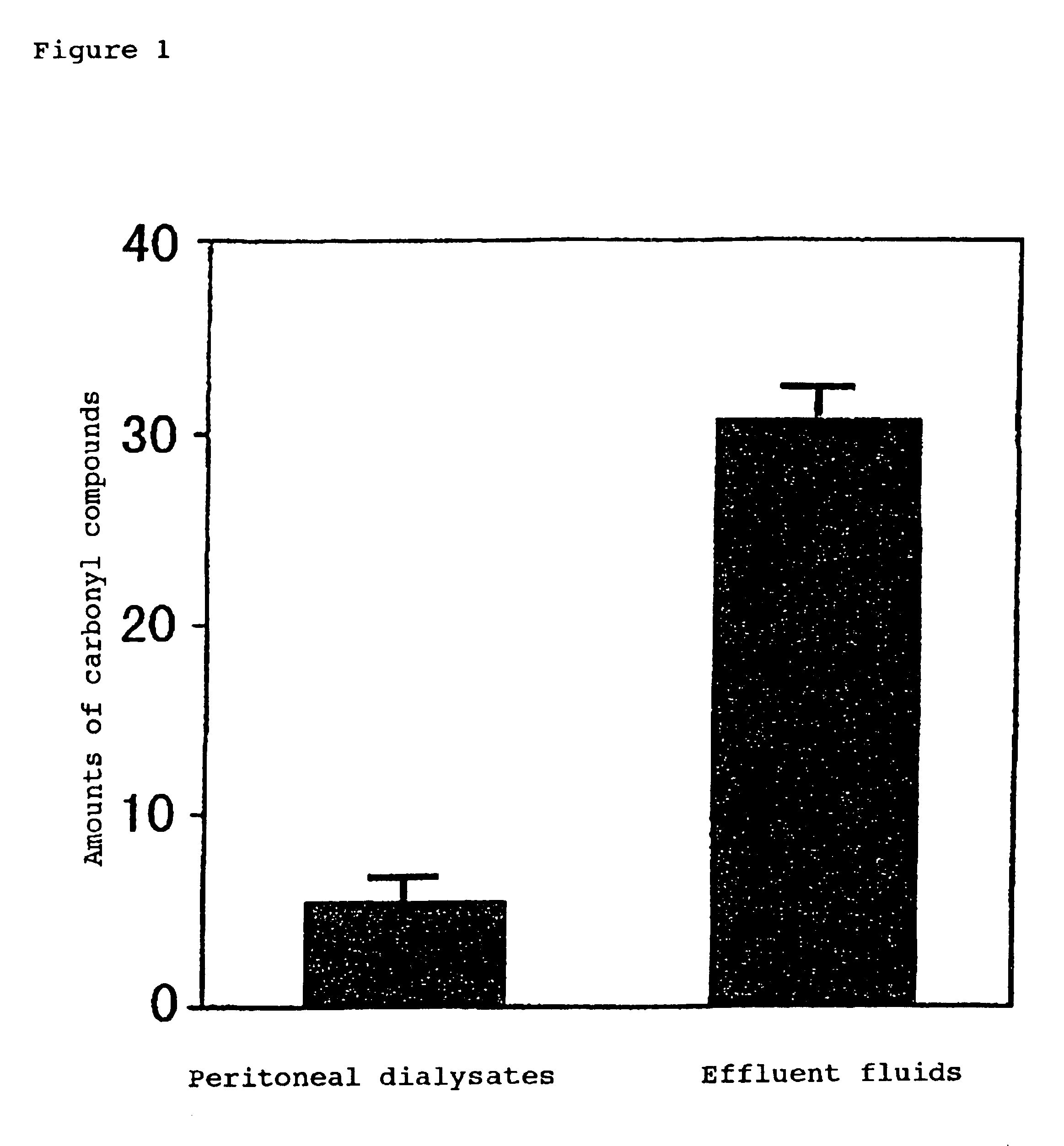
Measurement of the Amount of Carbonyl Compounds Present in the Peritoneal Dialysate and Peritoneal Dialysate Effluent

[0157]In order to demonstrate the generation of carbonyl stress in the peritoneal cavity, the amount of carbonyl compounds present in the peritoneal dialysate effluent was measured according to the following experiment method.

(i) Measurement of Carbonyl Compounds

[0158]After the peritoneal dialysate (Baxter Ltd.; Dianeal PD-2 2.5) had been administered to a peritoneal-dialysis patient and had been allowed to dwell in the peritoneal cavity overnight, the peritoneal dialysate effluent was collected from the patient. Aliquots (400 μl) of both the peritoneal dialysate and the peritoneal dialysate effluent were separately mixed with a 400-μl solution of 0.5 N hydrochloric acid containing 1.5 mM 2,4-dinitrophenylhydrazine (2,4-DNPH) (Wako Pure Chemical Industries, Ltd.), and the mixture was stirred at room temperature for 30 minutes to react the carbonyl compound with 2,4-DN...

example 2

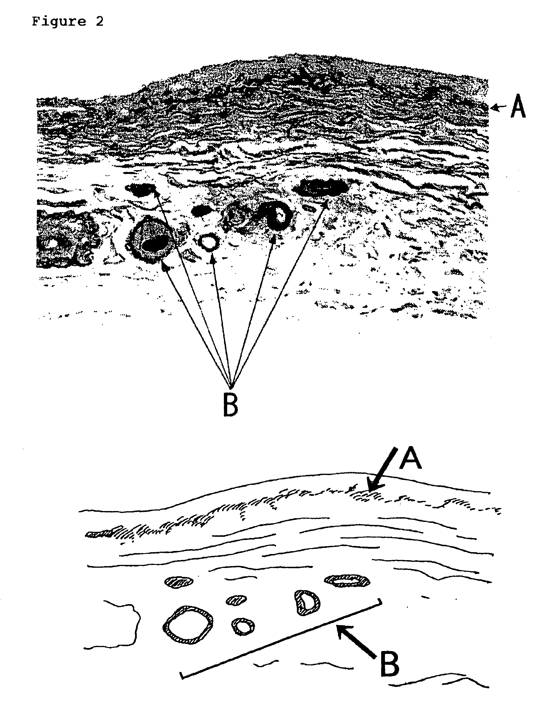
Histological Localization of Carbonyl-modified Proteins in the Peritoneum of a Peritoneal-dialysis Patient

[0162]The localization of carbonyl compounds in peritoneal tissues of a peritoneal-dialysis patient was studied by immunostaining using malondialdehyde as the index.

[0163]Peritoneal tissues from a peritoneal-dialysis patient (50-year-old male with a five-year history of peritoneal dialysis) were processed by immunostaining according to the method of Horie et al. (Horie, K. et al., J. Clin. Invest., 100, 2995-3004 (1997)). The primary antibody used was a mouse anti-malondialdehyde monoclonal antibody. The results showed that intense positive signals were present in the connective tissue under removed mesothelial cells, and the signals were also present on the thickened vascular wall (FIG. 2).

[0164]Malondialdehyde (MDA) is a carbonyl compound, which is generated by the degradation of peroxide lipid. Therefore, immunostaining was carried out by using antibodies against 4-hydroxy-2-...

example 3

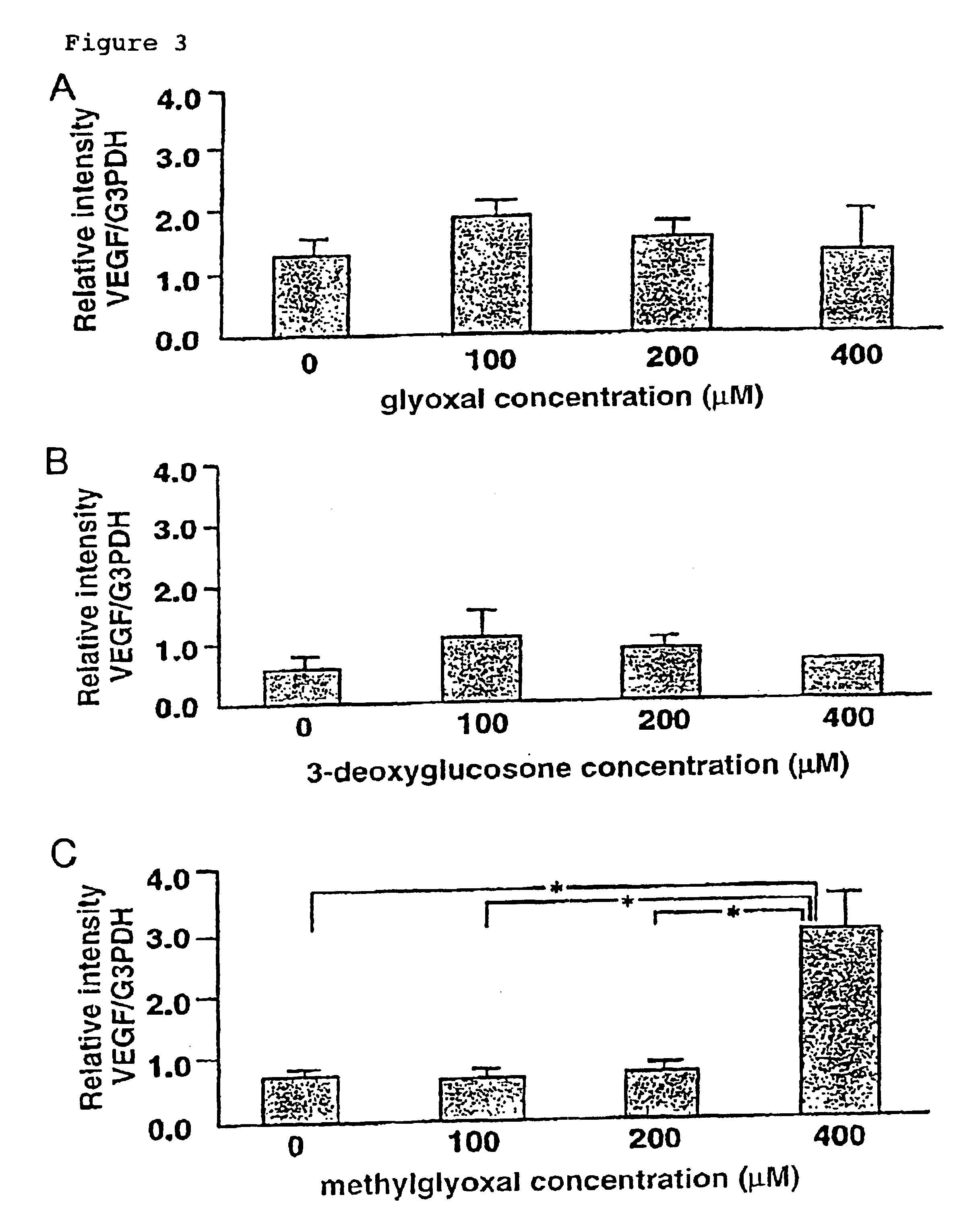
Peritoneal Cell Damages by Methylglyoxal

[0165]Decreased ultrafiltration of peritoneum by long-term peritoneal dialysis has been taken as evidence for an augmentation of the peritoneal surface area available for diffusive exchange (Krediet R T, Kidney Int, 55: 341-356 (1999); Heimburger O et al., Kidney Int, 38: 495-506 (1990); Imholz A L et al., Kidney Int, 43: 1339-1346 (1993); Ho-dac-Pannekeet M M et al., PeritDial Int, 17:144-150 (1997)). Namely, glucose in peritoneal dialysate flows out of peritoneal cavity by diffusion, thereby decreasing the dialytic function according to osmotic pressure gradient. An increased vascular surface area within the peritoneum might also account for this. In addition, the vascular endothelial growth factor (VEGF) might play a critical role in this pathology. VEGF increases vascular permeability (Senger D R et al., Science 219: 983-985 (1983); Connolly D T et al., J Biol Chem, 264: 20017-20024 (1989)), stimulates nitric oxide (NO) synthesis and vasod...


PUM

PropertyMeasurementUnit
period of timeaaaaaaaaaa
dwelling timeaaaaaaaaaa
timeaaaaaaaaaa

Abstract

Carbonyl compounds generated and accumulated in the peritoneal dialysate can be inactivated or eliminated by a carbonyl compound-trapping agent such as aminoguanidine. Carbonyl compounds generated during sterilization and storage of the peritoneal dialysate can be eliminated by pre-contacting with the trapping agent. Further, it is possible to eliminate carbonyl compounds transferred from the blood to the peritoneal cavity of the patient during peritoneal dialysis treatment, by adding the trapping agent to the peritoneal dialysate or by circulating the fluid through a carbonyl compound-trapping cartridge. Intraperitoneal protein modification by carbonyl compounds is inhibited by the present invention, thereby sufficiently reducing peritoneal disorders associated with peritoneal dialysis treatment.

Description

CROSS REFERENCES[0001]This application is the national phase application of PCT application PCT / JP99 / 04521 filed Aug. 23, 1999 designating the United States which application claims priority to Japanese patent applications 10 / 237108 filed Aug. 24, 1998 and 11 / 155393 filed Jun. 2, 1999 to which applications is claimed priority.TECHNICAL FIELD[0002]The present invention relates to a peritoneal dialysate used for treating patients with renal failure.BACKGROUND ART[0003]Two types of dialysis, hemodialysis and peritoneal dialysis, are used to treat patients with chronic renal failure. Peritoneal dialysis is a method in which the dialysate is allowed to dwell in the peritoneal cavity for a certain period of time, thereby facilitating the excretion of waste products out of the body into the dialysate through the peritoneum. The dialysate is then recovered. Peritoneal dialysis is subdivided into intermittent peritoneal dialysis (IPD) and continuous ambulatory peritoneal dialysis (CAPD). CAP...

Claims


Application Information

Patent Timeline
Patent Type & Authority Patents(United States)
IPC IPC(8): A61K31/155A61M1/28
CPCA61K31/155A61K31/203A61K31/4965A61K33/00A61M1/287A61K2300/00Y10S514/866Y10S514/832A61P13/12A61P43/00A61P7/08A61K31/44
Inventor MIYATA
Owner MIYATA TOSHIO
Why Eureka
Try Eureka