
Waste heat recovery means for fuel cell power system

a fuel cell power system and heat recovery technology, applied in the direction of cell components, electrochemical generators, cell component details, etc., can solve the problems of large amount of energy needed for fuel processing, difficulty in dissipating waste heat generated by the fuel cell stack, and large use of fuel cell power systems, so as to facilitate heat transfer, reduce the total thermal energy required for fuel reformers, and reduce the effect of energy consumption

Inactive Publication Date: 2005-08-09
CAO YIDING
View PDF1 Cites 17 Cited by
  • Summary
  • Abstract
  • Description
  • Claims
  • Application Information

AI Technical Summary

Benefits of technology

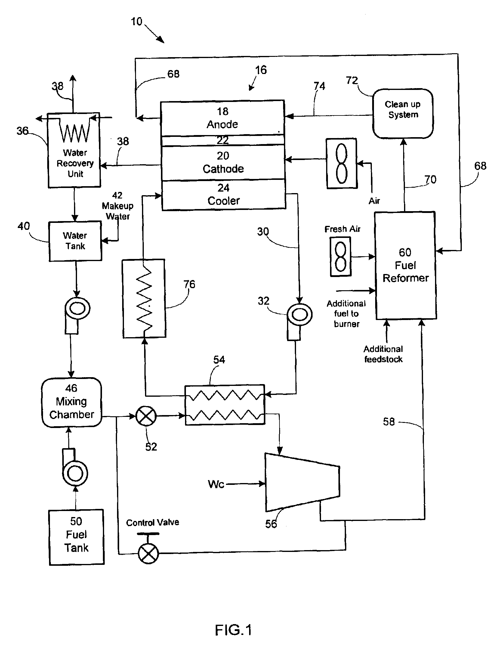
[0004]It is an objective of the present invention to provide an energy recovery system which recovers the waste heat generated by the fuel cell stack and uses it for fuel processing purposes, thereby the total thermal energy required for the fuel reformer is substantially reduced and the efficiency of a fuel cell power system employing said energy recovery system is significantly increased. The energy recovery system comprises an expansion valve, a heat exchanger that facilitates the heat transfer between the feedstock and the cooling medium of the fuel cell stack, and a compressor system. After flowing through the expansion valve, the pressure of the feedstock to the heat exchanger is reduced to a sufficiently low level, and the feedstock is vaporized in the heat exchanger while absorbing heat from the cooling medium of the fuel cell stack. At the outlet of the heat exchanger, the feedstock is substantially vaporized, and is subsequently compressed to a sufficiently high pressure by the compressor system before it is delivered to the fuel reformer, The feedstock could be water, fuel, or the mixture of water and fuel. Since the latent heat of vaporization is provided through the thermal energy recovered from the waste heat generated by the fuel cell stack, the heat input to the fuel reformer for the endothermic reaction in the reformer is substantially reduced, and subsequently the fuel efficiency of the fuel cell power system is substantially improved.
[0005]Another objective of this invention is to provide a heat dissipation means for the waste heat generated by the fuel cell stack. During the heat transfer process within the heat exchanger in the energy recovery system, a substantially large portion of the heat which is removed from the fuel cell stack is transferred to the feedstock. As a result, the fuel cell stack can be adequately cooled with a much smaller cooling device such as a radiator requiring a much smaller heat dissipation capacity and consuming much smaller power for the cooling fan. In some situation, a radiator for the heat dissipation could be completely eliminated.

Problems solved by technology

Although a fuel cell operating on pure hydrogen gas is considered to be the ultimate clean energy system, the difficulties associated with handling high-pressure compressed hydrogen gas and the lack of a hydrogen infrastructure would prevent the mass use of the fuel cell power system in the foreseeable future.
One of the drawbacks for reformate based fuel cell power systems is that a large amount of energy is needed for the fuel processing purpose.
Another problem generally associated with a PEM fuel cell power system is the difficulty in dissipating the waste heat generated by the fuel cell stack.

Method used


Image

  • Waste heat recovery means for fuel cell power system
  • Waste heat recovery means for fuel cell power system
  • Waste heat recovery means for fuel cell power system

Examples


Embodiment Construction

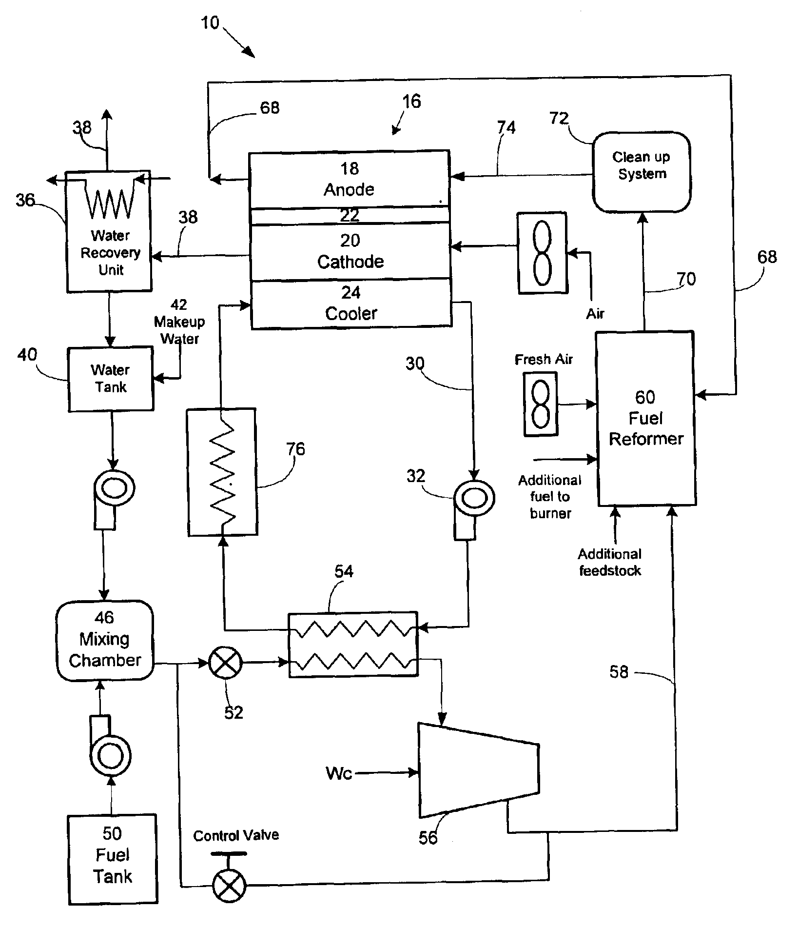
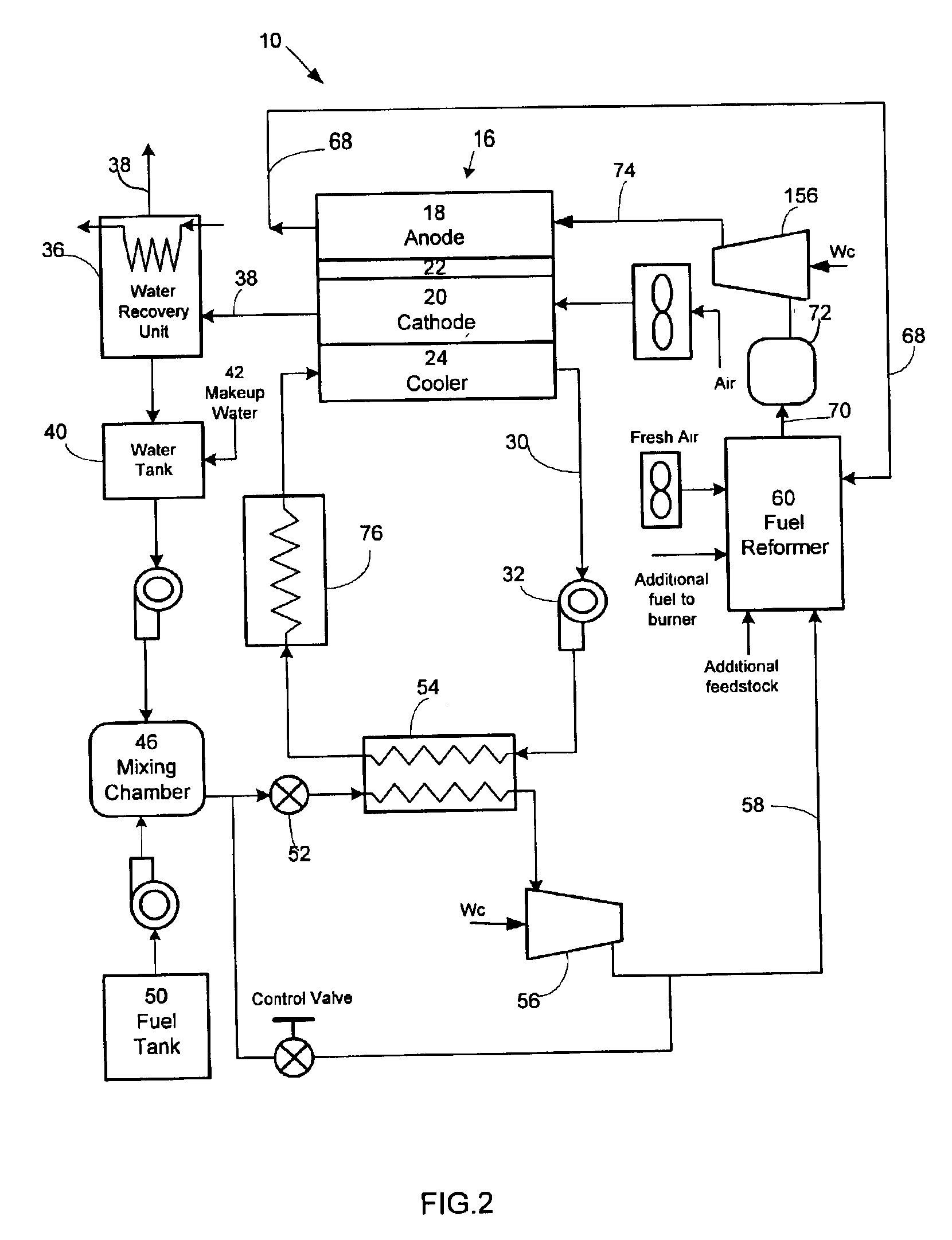
[0010]With reference to FIG. 1, which illustrates a reformate / air fuel cell power system 10 according to a preferred form of the present invention. The fuel cell power system 10 generally comprises at least a fuel cell stack 16 which includes at least an anode electrode 18, a cathode electrode 20, an electrolyte 22 such as a proton exchange membrane (PEM) between the anode and cathode, and a cooler section 24. The cooler section 24 could be integrated with a close-looped cooling system 30 with a coolant pump 32 which circulates a liquid coolant within the loop to remove the waste heat from the fuel cell stack, as shown in FIG. 1. Alternatively, the cooler section could be integrated with a heat pipe device which removes the waste heat from the fuel cell stack through the two-phase heat transfer mechanism, or an open-looped air cooling system to remove the waste heat from the fuel cell stack (not shown). A water recovery unit 36 recovers water from the cathode exhaust air stream 38 a...


PUM

PropertyMeasurementUnit
temperatureaaaaaaaaaa
pressureaaaaaaaaaa

Abstract

A fuel cell power system includes at least a fuel cell stack, a cooling means which removes the waste heat generated within the fuel cell stack, a fuel reformer which reforms a hydrocarbon for the fuel supply to the fuel cell stack, and an energy recovery system, which includes an expansion valve for reducing the pressure of the feedstock to the energy recovery system, a heat exchanger for facilitating the heat transfer from the cooling means of the fuel cell stack to the feedstock of the energy recovery system, and at least a compressor for raising the pressure of the feedstock to a sufficiently high level and delivering the feedstock to the fuel reformer, thereby a substantially large portion of the waste heat is recovered and used to vaporize the feedstock. As a result, the fuel utilization of the fuel cell power system is significantly improved due to a reduced heat input to the fuel reformer, and the size of the radiator and the associated power consumption for dissipating the waste heat into the surroundings is substantially reduced.

Description

CROSS REFERENCES TO RELATED APPLICATIONS[0001]This application is a continuation of provisional application No. 60 / 329,858 filed Oct. 18, 2001.BACKGROUND OF THE INVENTION[0002]A fuel cell is a device that directly converts the chemical energy of reactants (a fuel and an oxidant) into low-voltage d.c. electricity. Many of the operational characteristics of fuel cell systems are superior to those of conventional power generation. Among several distinct types of fuel cells, the polymer electrolyte membrane or proton exchange membrane (PEM) fuel cell is most popular for transportation and portable applications. The PEM fuel cell could employ compressed hydrogen gas or methanol reformate as fuel. Other hydrocarbons, such as gasoline, diesel fuel, or ethanol could also be reformed to produce suitable reformate for the fuel cell (U.S. Pat. No. 5,928,614 of Autenrieth and Heil, U.S. Pat. No. 4,865,624 of Okada, U.S. Pat. No. 5,984,986 of Weisheu et al., U.S. Pat. No. 5,651,800 of Mizuno et ...

Claims


Application Information

Patent Timeline
Patent Type & Authority Patents(United States)
IPC IPC(8): H01M8/04H01M8/06
CPCH01M8/04022H01M8/04089H01M8/0612Y02E60/50
Inventor CAO, YIDING
Owner CAO YIDING
Learn More