
Heating apparatus using induction heating

a technology of induction heating and heating apparatus, applied in the field of heating apparatus, can solve the problems of affecting throughput, lowering temperature, and theoretically unsuitable apparatuses for and achieve the effect of rapid raising or lowering temperature of wafers and high volume processing

Inactive Publication Date: 2005-08-23
KOBE STEEL LTD
View PDF18 Cites 8 Cited by
  • Summary
  • Abstract
  • Description
  • Claims
  • Application Information

AI Technical Summary

Benefits of technology

[0015]To cope with these disadvantages, this invention is intended to provide a heating apparatus which is installed in a low pressure CVD system or annealing equipment for use in semiconductor integrated circuit manufacturing processes for heat-treating wafers on which IC's are to be formed, wherein wafers are uniformly heated, the temperature of wafers is rapidly raised or lowered, and wafers are processed in high volume.
[0019]The heating apparatus of the invention is provided with the cylindrical body made of glass-like carbon as heating element. Glass-like carbon (GLC) is obtained by curing thermosetting resin as raw material and carbonizing the material in an inert atmosphere or in vacuum. Like ordinary carbon materials, glass-like carbon has such properties as lightness in weight, heat resistance, corrosion resistance, and electrical conductivity. In addition, glass-like carbon has such advantages as high purity, high strength (mirror-polishable), gas impermeability, and low particle and gas emission capability. On this account, the cylindrical body made of glass-like carbon placed in the reactor does not emit impurity particles or gas, and absorbs less gas and is chemically stable. Therefore, wafers are prevented from being contaminated even under high-temperature, corrosive reaction conditions. While glass-like carbon has an amorphous, uniform, continuous, and dense texture, graphite materials have a structure comprising aggregates of carbon powder particles. For this reason, graphite materials pose problems, such as the production of carbon powder and emission of occluded gas during reaction.
[0020]Since the cylindrical body made of glass-like carbon is caused to produce heat by electrical currents produced by high-frequency induction, the cylindrical body is capable of rapidly raising the temperature. Meanwhile, since the cylindrical body is made of glass-like carbon having a property of low thermal capacity, the cylindrical body is capable of rapidly lowering the temperature. Further, since the cylindrical body is made of glass-like carbon that has an amorphous, uniform, continuous, and dense texture and is excellent in thermal conductivity, the cylindrical body made of glass-like carbon is excellent in temperature uniformity. Further, the cylindrical body made of glass-like carbon can be fabricated in such size that batch processing, in which a large number of wafers are processed at a time, can be implemented. As mentioned above, the heating apparatus of the invention can be installed in low pressure CVD systems, annealing equipment, and the like for use in semiconductor integrated circuit manufacturing processes, and is capable of uniformly heating wafers and rapidly raising and lowering the temperature of wafers as well as processing wafers in high volume.
[0021]In the heating apparatus with a heat insulating body placed between the cylindrical body made of glass-like carbon and the high-frequency induction coil or around the high-frequency induction coil, the quantity of heat escaping from the cylindrical body made of glass-like carbon to the outside of the reactor can be reduced, and this contributes to the enhancement of heating efficiency (heat utilization).
[0022]As mentioned above, the heating apparatus of the invention comprises the cylindrical body made of glass-like carbon placed inside a reactor and the high-frequency induction coil that is placed outside the reactor and is for causing the cylindrical body made of glass-like carbon to produce heat and thereby heating objects to be heated in the reactor. Therefore, when the heating apparatus of the invention is installed in a low pressure CVD system or annealing equipment for use in semiconductor integrated circuit manufacturing processes for heat-treating wafers on which IC's are to be formed, the wafers are uniformly heated, the temperature of wafers is rapidly raised and lowered, and further, wafers are processed in high volume, which is not the case with systems using a conventional heating apparatus based on high-frequency induction heating. Thus, furnishing a low pressure CVD system or annealing equipment with the heating apparatus of the invention significantly shortens time required for high-volume processing of wafers and enhances the productivity, as compared with cases where a conventional electrical resistance heater is used. With the heating apparatus of the invention provided with the heat insulating body, the quantity of heat escaping from the cylindrical body made of glass-like carbon to the outside of the reactor is reduced, and this contributes to the enhancement of heating efficiency (heat utilization).

Problems solved by technology

However, in the above-mentioned heating apparatuses wherein heating is provided by radiant heat or conductive heat from a heater, there is restriction due to thermal conduction between the output of the heater and wafers as objects to be heated.
As shown in Table 1, therefore, these apparatuses are theoretically unsuitable for rapidly raising or lowering the temperature.
Thus, these apparatuses have a disadvantage that it takes much time to rise and lower the temperature of wafers and this leads to impaired throughput.
As shown in Table 1, these apparatuses have a disadvantage that the apparatuses are incapable of processing wafers in high volume.
Therefore, these apparatuses have a disadvantage that they are incapable of processing wafers in high volume.

Method used


Image

  • Heating apparatus using induction heating
  • Heating apparatus using induction heating
  • Heating apparatus using induction heating

Examples


Embodiment Construction

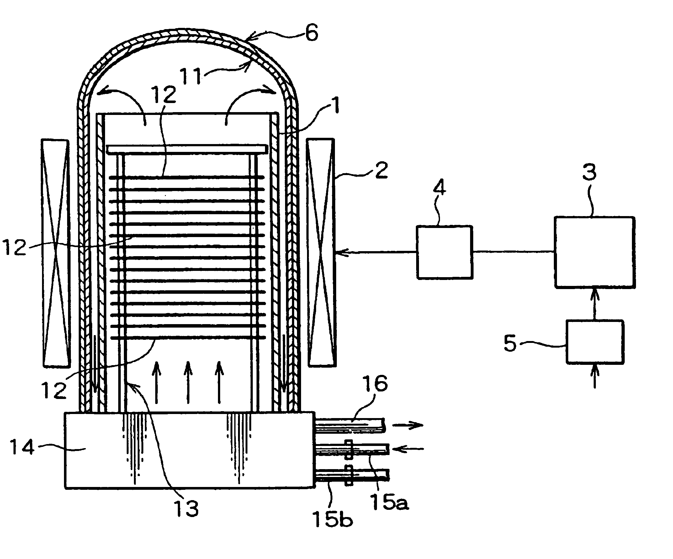
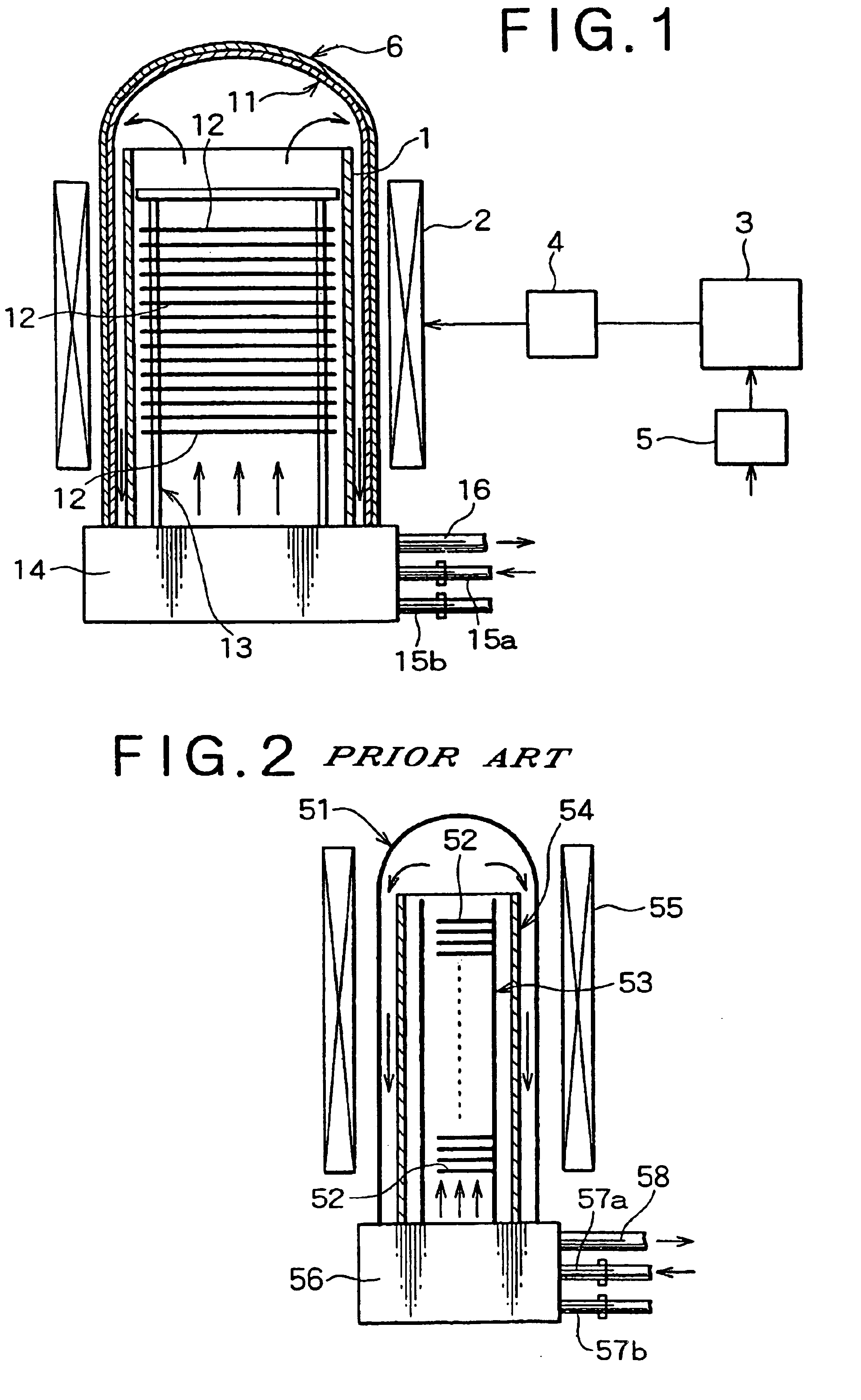
[0028]An explanation is given below about an embodiment of the invention, referring to the accompanying drawing. FIG. 1 is a schematic diagram illustrating an example of vertical low pressure CVD systems equipped with the heating apparatus of the invention.

[0029]As shown in FIG. 1, this batch processing vertical low pressure CVD system is provided with a reactor 11 made of quartz having circular hollow cross-sections and dome-shaped, closed top; a cylindrical body 1 made of glass-like carbon which is placed in the reactor 11 and is an inner tube formed in cylindrical shape; a boat 13 which is placed inside the cylindrical body 1 made of glass-like carbon and is designed to be mounted with a large number of vertically arranged wafers 12; and a manifold 14. The vertical low pressure CVD system is further provided with a heat insulating body 6 made of carbon fiber felt covering the reactor 11; an air-core-type, high-frequency induction coil 2 placed concentrically with the reactor 11 c...


PUM

PropertyMeasurementUnit
Heataaaaaaaaaa

Abstract

A heating apparatus which is installed in a low pressure CVD system or annealing equipment for use in semiconductor integrated circuit manufacturing processes for heat-treating wafers on which IC's are to be formed, wherein wafers are uniformly heated, the temperature of wafers is rapidly raised and lowered, and wafers are processed in high volume, wherein the apparatus comprises a cylindrical body made of glass-like carbon placed inside a reactor, and a high-frequency induction coil which is placed outside the reactor and is for causing the cylindrical body made of glass-like carbon to produce heat and thereby heating wafers in the reactor.

Description

BACKGROUND OF THE INVENTION[0001]1. Field of the Invention[0002]This invention relates to a heating apparatus which is installed in, for example, a low pressure CVD system and is suitable for heat treatment on wafers.[0003]2. Description of Related Art[0004]As is commonly known, a semiconductor integrated circuit manufacturing process involves a variety of IC process units, including oxidation and dispersion equipment, vapor phase epitaxial growth systems, low pressure CVD systems (LPCVD systems), and annealing equipment. These units are equipped with heating apparatuses for heat-treating silicon wafers (hereafter, simply referred to as “wafers”) on which IC's are being formed or to be formed.[0005]FIG. 2 is a schematic diagram illustrating an example of vertical low pressure CVD systems equipped with a heater based on electric resistance heating as heating apparatus, for the purpose of explanation of prior arts. In low pressure CVD, films are generally formed at temperature of 400 ...

Claims


Application Information

Patent Timeline
IPC IPC(8): H05B6/02C23C16/46H01L21/205H05B6/10H01L21/324
CPCH05B6/108H01L21/324
Inventor HAMAGUCHI, MAKI
Owner KOBE STEEL LTD
Learn More