Heat sink material and method of manufacturing the heat sink material

a heat sink and heat sink technology, applied in the field of heat sink materials, can solve the problems of large electric power consumption per operation area of semiconductors, insufficient release of generated heat amount, and an enemy of heat for ic chips

Inactive Publication Date: 2005-08-23
NGK INSULATORS LTD
View PDF56 Cites 53 Cited by
  • Summary
  • Abstract
  • Description
  • Claims
  • Application Information

AI Technical Summary

Benefits of technology

[0016]The present invention has been made taking the foregoing problems into consideration, and an object thereof is to provide a heat sink material which makes it possible to obtain characteri

Problems solved by technology

In general, heat is an enemy for the IC chip and it is necessary that the internal temperature thereof does not exceed the maximum allowable junction temperature.
The electric power consumption per operation area is large in the semiconductor device such as a power transistor or a semiconductor rectifier element.
Therefore, the generated heat amount cannot be sufficiently released with only the heat amount released from a case (package) and a lead of the semiconductor device.
It is feared that the internal temperature of the device may be raised to cause thermal destruction.
When the IC chip has such a large size, it is

Method used


Image

  • Heat sink material and method of manufacturing the heat sink material
  • Heat sink material and method of manufacturing the heat sink material
  • Heat sink material and method of manufacturing the heat sink material

Examples


first embodiment

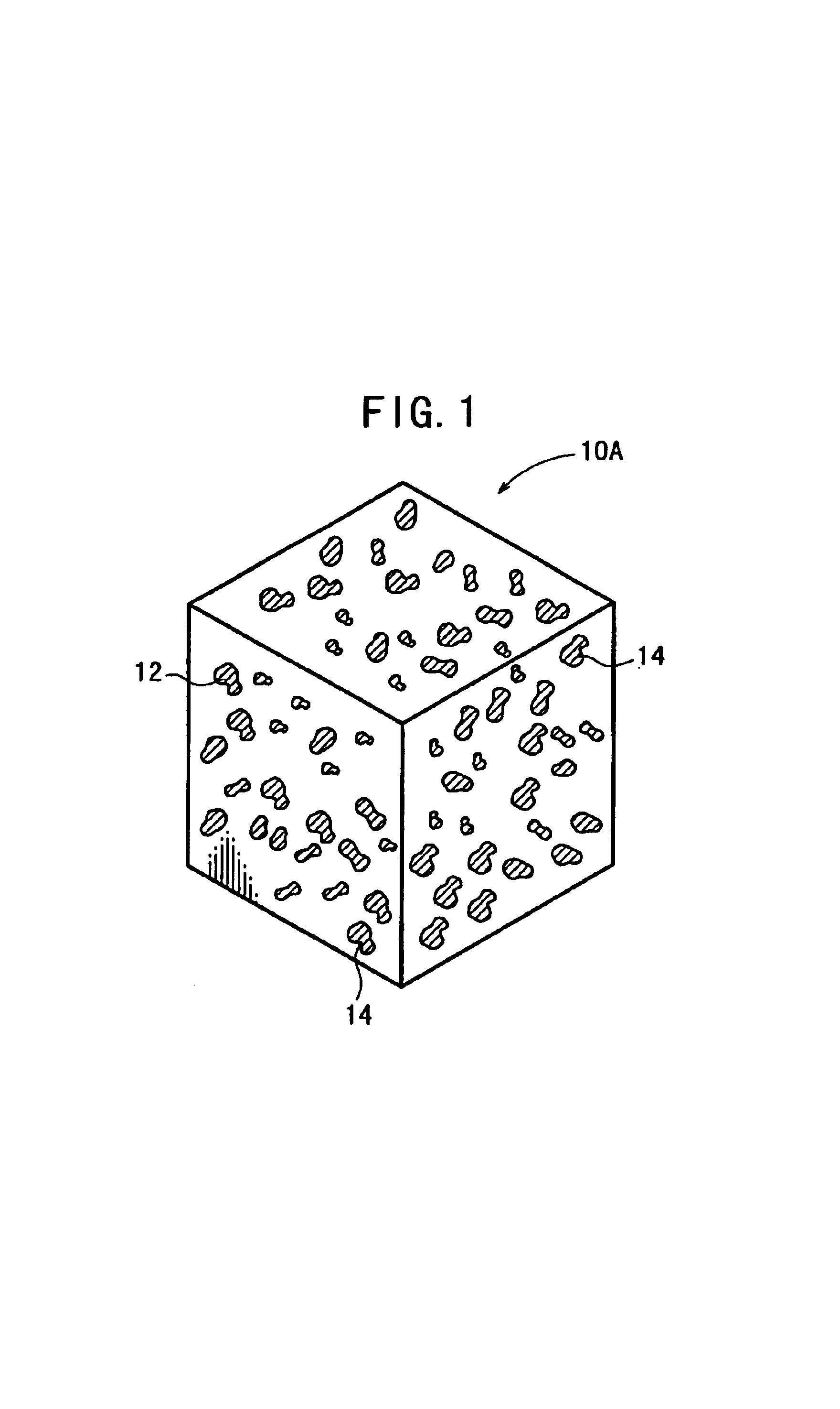
[0102]As shown in FIG. 1, a heat sink material 10A comprises a porous sintered member 12 obtained by sintering carbon or allotrope thereof to form a network, in which the porous sintered member 12 is infiltrated with metal 14.

[0103]In this case, the carbon preferably used or the allotrope thereof has a coefficient of thermal conductivity of not less than 100 W / mK, desirably not less than 150 W / mK (estimated value in a state in which no pore exists), and more desirably not less than 200 W / mK (estimated value in a state in which no pore exists).

[0104]This embodiment is illustrative of a case of the heat sink material in which open pores of the porous sintered member 12 of graphite having a coefficient of thermal conductivity of not less than 100 W / mK are infiltrated with copper. Those usable as the metal 14 of infiltration other than copper include aluminum and silver.

[0105]As for the volume ratios of the porous sintered member 12 and the metal 14, the volume ratio of the porous sint...

second modified embodiment

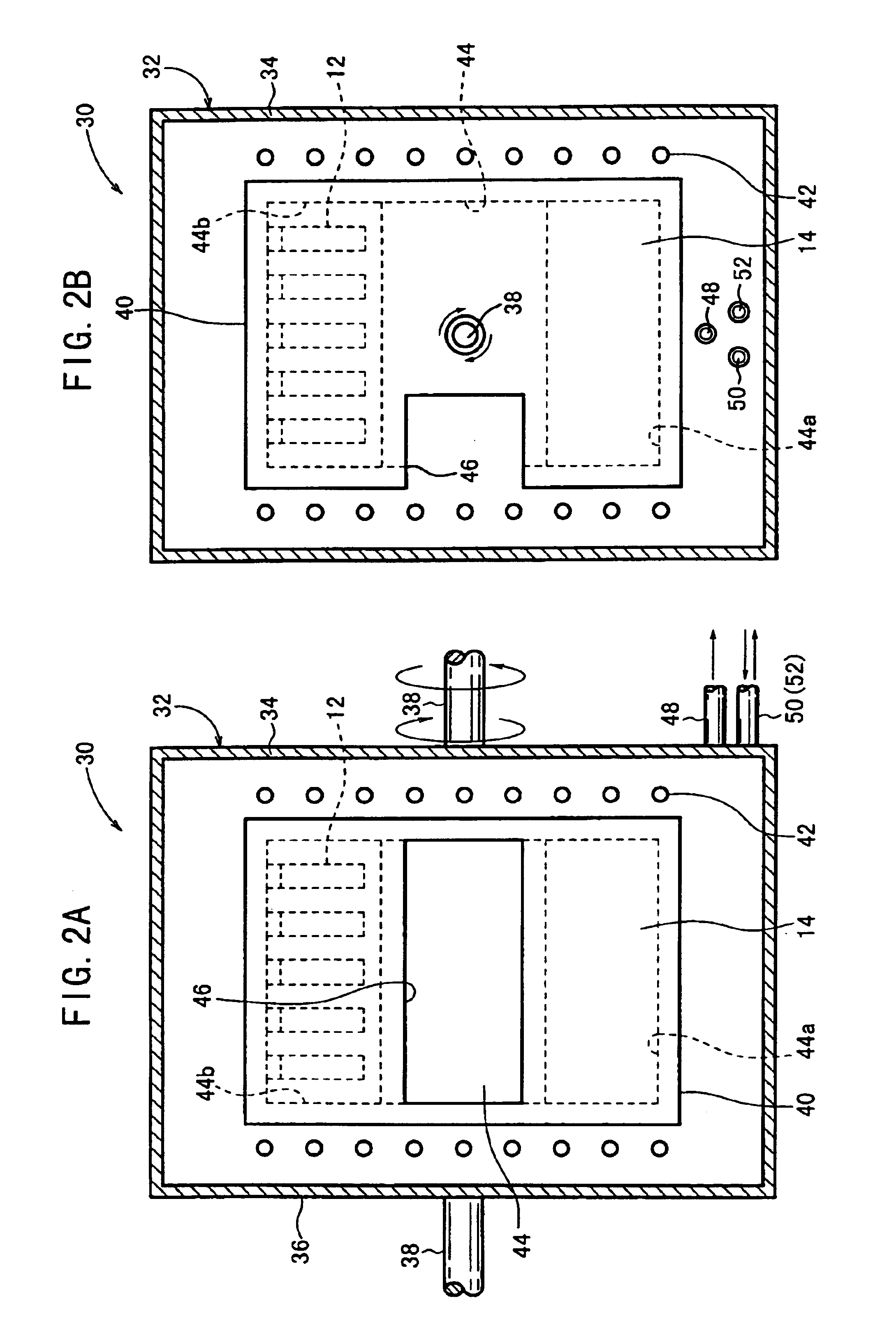
[0156]Next, the second modified method will be explained with reference to FIG. 5. In an infiltrating step of the second modified embodiment, the high pressure vessel 30 is used, which includes a partition plate (not shown) composed of a porous ceramic material provided at a central portion in the refractory vessel 40 installed in the high pressure vessel 30. The interior of the refractory vessel 40 is comparted by the partition plate into a first chamber 44a and a second chamber 44b.

[0157]As for the partition plate, it is desirable to use a porous ceramic material having the porosity of 40 to 90% by volume, and the pore diameter of 0.5 to 3.0 mm. More preferably, it is desirable to use a porous ceramic material having the porosity is 70 to 85% by volume, and the pore diameter of 1.0 to 2.0 mm.

[0158]In the second modified embodiment, as shown in FIG. 5, graphite is firstly sintered to prepare a porous sintered member 12 of graphite (step S201). For the initial state, the high press...

second embodiment

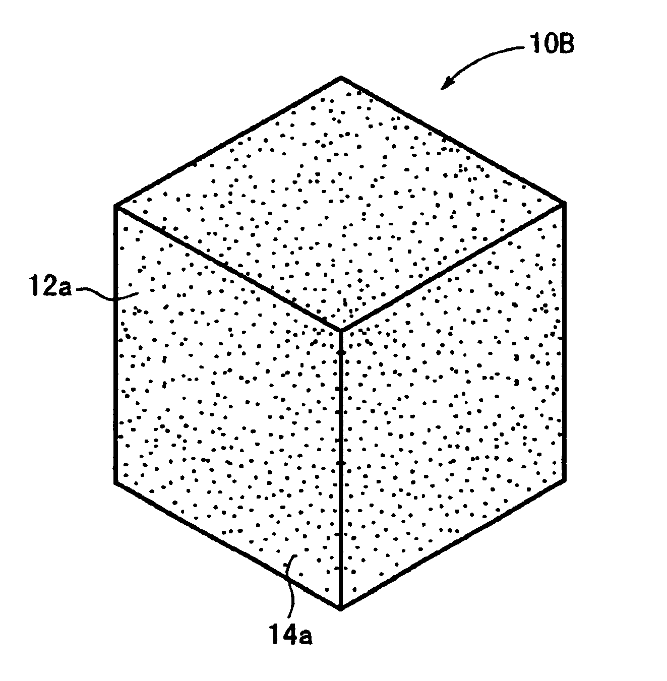
[0173]Next, a heat sink material 10B will be explained with reference to FIG. 9.

[0174]As shown in FIG. 9, the heat sink material 10B according to the second embodiment is constructed by mixing powder 12a of carbon or allotrope thereof and powder 14a of metal 14, and forming an obtained mixture at a predetermined temperature under a predetermined pressure.

[0175]Those preferably used as the carbon or the allotrope thereof are those having a coefficient of thermal conductivity of not less than 100 W / mK, desirably not less than 150 W / mK (estimated value when no pore exists), and more desirably not less than 200 W / mK (estimated value when no pore exists). Especially, in the second embodiment, it is possible to use diamond other than graphite. This embodiment is illustrative of the heat sink material 10B constructed by mixing powder of copper and powder of graphite having a coefficient of thermal conductivity of not less than 100 W / mK, and forming an obtained mixture. It is possible to u...


PUM

PropertyMeasurementUnit
Temperatureaaaaaaaaaa
Poweraaaaaaaaaa
Poweraaaaaaaaaa

Abstract

Graphite is placed in a case, and the case is set in a furnace. The interior of the furnace is subjected to sintering to produce a porous sintered member of graphite. After that, the case with the porous sintered member therein is taken out of the furnace, and is set in a recess of a press machine. Subsequently, molten metal of metal is poured into the case, and then a punch is inserted into the recess to forcibly press the molten metal in the case downwardly. Open pores of the porous sintered member are infiltrated with the molten metal of the metal by the pressing treatment with the punch.

Description

TECHNICAL FIELD[0001]The present invention relates to a heat sink material for construction a heat sink which efficiently releases heat generated, for example, from an IC chip, and a method of producing the same.BACKGROUND ART[0002]In general, heat is an enemy for the IC chip and it is necessary that the internal temperature thereof does not exceed the maximum allowable junction temperature. The electric power consumption per operation area is large in the semiconductor device such as a power transistor or a semiconductor rectifier element. Therefore, the generated heat amount cannot be sufficiently released with only the heat amount released from a case (package) and a lead of the semiconductor device. It is feared that the internal temperature of the device may be raised to cause thermal destruction.[0003]This phenomenon also occurs in the same manner in the IC chip which carries a CPU. The amount of heat generation is increased during the operation in proportion to the improvemen...

Claims


Application Information

Patent Timeline
IPC IPC(8): H01L21/48H01L23/34H01L21/02H01L23/373B22F3/14C04B35/52C04B35/565C04B35/65C04B35/653C04B38/06C04B41/45C04B41/88C22C1/10C22C29/00
CPCB22F3/14C04B35/565C04B35/65C04B35/653C04B38/0615C04B41/009C04B41/4523C04B41/88C22C1/1036C22C29/00H01L21/4871H01L23/373H01L23/3733C04B35/522C04B35/52C04B38/0051C04B38/0058C04B38/0074C04B41/5127C04B41/5155C04B41/5116C04B38/00Y10T428/30C04B2111/00844C04B2235/3817C04B2235/40C04B2235/402C04B2235/404C04B2235/407C04B2235/425C04B2235/5427C04B2235/5436C04B2235/77C04B2235/80C04B2235/96C04B2235/9607C22C2001/1073H01L2924/0002H01L2924/00Y10T428/249967Y10T428/249957C22C1/1073
Inventor ISHIKAWA, SHUHEIMITSUI, TSUTOMUSUZUKI, KENNAKAYAMA, NOBUAKITAKEUCHI, HIROYUKIYASUI, SEIJI
Owner NGK INSULATORS LTD
Why Eureka
Try Eureka