Exhaust sound and emission control systems

a technology for exhaust sound and emission control, applied in the direction of machines/engines, instruments, heat measurement, etc., can solve the problems of adversely affecting the environment, not being combined into a single unit, and ever-increasing volume of automobile and truck traffic generating exhaust emissions, so as to enhance emissions reduction and reduce exhaust components

Inactive Publication Date: 2005-08-30
MAROCCO GREGORY M
View PDF46 Cites 80 Cited by
  • Summary
  • Abstract
  • Description
  • Claims
  • Application Information

AI Technical Summary

Benefits of technology

[0055]The exhaust sound and emission control systems of the present invention comprise a series of devices for attenuating sound and noxious emissions primarily for, but not limited to, an automobile exhaust system. In one aspect, the system relates to a catalytic converter and resonator combination, combined within a single canister or shell. The combination device may be installed between the engine and a muffler at or near the downstream or exhaust outlet end of the exhaust system, with the system perhaps including an additional catalytic converter(s) upstream of the catalytic converter and resonator combination. The

Problems solved by technology

By the time of the 1950s, it was becoming apparent that the ever-increasing volume of automobile and truck traffic was generating exhaust emissions which were adversely affecting the environment.
However, long before the recognition of chemical or particulate automobile exhaust emissions as a hazard, another type of automobile exhaust emission had been recognized, i.e., noise or sound.
These two types of emissions control devices, i.e., catalytic converters and mufflers or other sound attenuating devices, have generally not been combined into a single unit due to conflicting characteristics and physical requirements.
Very high temperatures cause the aluminized coating to be burned off, and cause both the interior and (after removal of any coating) exterior to be oxidized, to the point of burn-through or rust-through, in relatively short order.
While mufflers and other related devices have been constructed of stainless steel in order to reduce oxidation problems, these devices are relatively costly due to the material used and the difficulty in working with such material, in comparison to mild steel.
On the other hand, catalytic converters require relatively high temperatures for efficient operation.
Thus, most catalytic converters are constructed of relatively costly materials in order to withstand the heat generated therein.
However, heretofore no combining of a catalytic converter and a resonator has been accomplished, to the knowledge of the present inventor.
It is also noted that mufflers and resonators have generally not been combined into a single unit due to conflicting characteristics and physical requirements.
It is also known that the combustion products of leaded fuels will contaminate the catalytic elements of a catalytic converter, rendering it ineffective in a very few miles of vehicle operation using such leaded fuels.
Moreover, the entrainment of ambient air through the outer shell of the Kazokas device has the effect of lowering the internal temperature within the device, thereby lessening the efficiency of the peripherally disposed catalytic conversion material along the inner shell.
Such devices cannot serve as resonators, as they lack the multiple pathways required to cause different frequencies to occur, and to cancel those frequencies, thereby reducing the noise output of the system.
Moreover, Ignoffo uses a series of bolts installed through flanges, making the operation even more cumbersome.
(It is noted that mufflers are inherently pressurized somewhat higher than ambient when in operation, due to the backpressure created in such devices, yet Bailey et

Method used


Image

  • Exhaust sound and emission control systems
  • Exhaust sound and emission control systems
  • Exhaust sound and emission control systems

Examples


embodiment 10

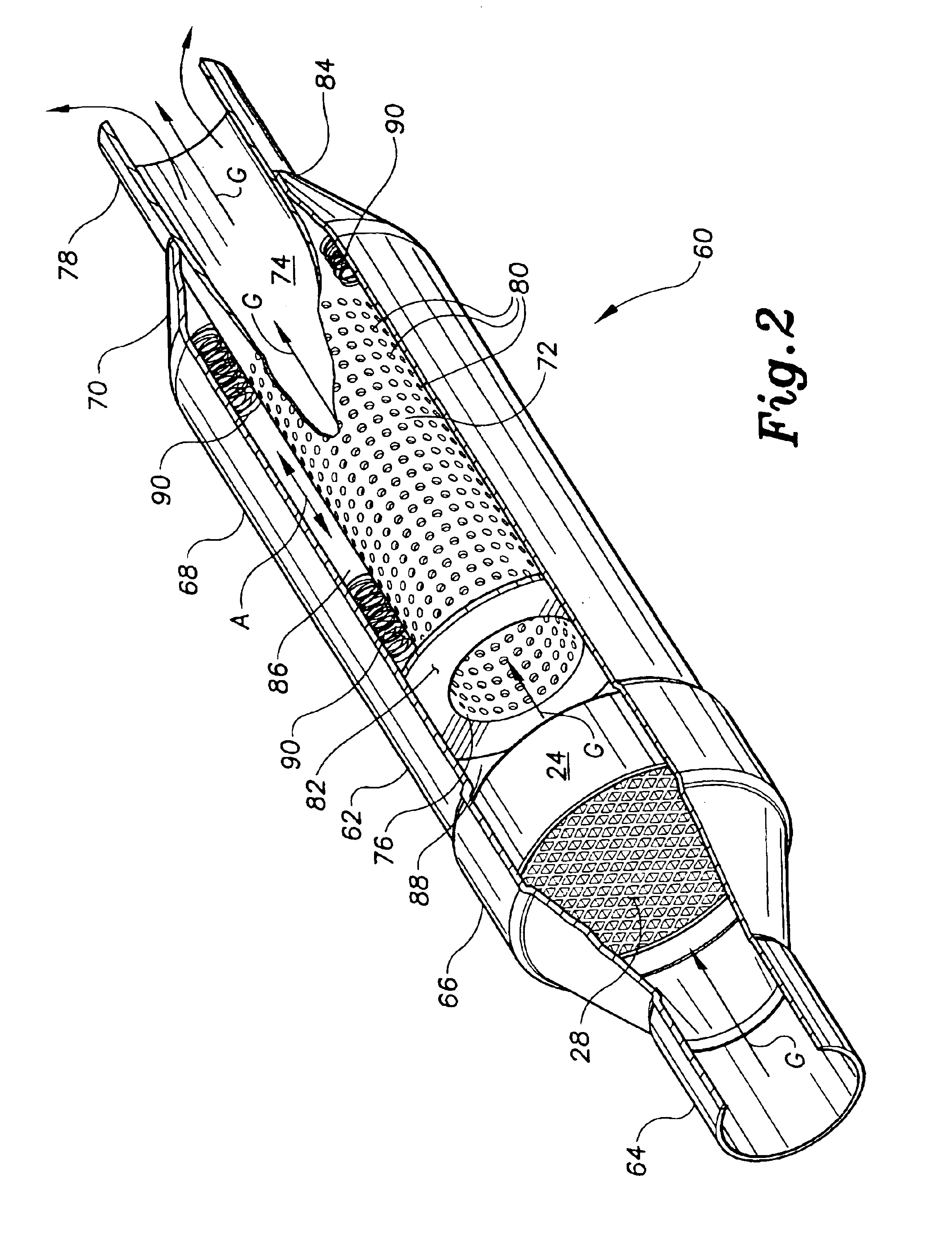
[0109]The remainder of the catalytic converter and resonator combination 60 of FIG. 2 is constructed similarly to the embodiment 10 of FIG. 1, with the resonator element 72 having an outer diameter substantially less than the inner diameter of the rear portion 68 of the canister 62. This difference between the inner diameter of the canister rearward portion 68 and the outer diameter of the resonator element 72, defines a sound attenuating plenum 86 therebetween. A forward sound attenuating plenum 88 is also defined between the rear of the catalytic converter element 24 and the forward end 76 of the resonator element 72 and its supporting front plate 82, within the outer shell 62 of the combination catalytic converter and resonator device 60.

[0110]The toroidal front plate 82, along with the necked down rearward end 84 of the conical rearward portion 70 of the shell 62, serve to secure the resonator pipe element 72 concentrically within the rearward portion 68 of the canister 62, with...

embodiment 100

[0118]Each of the catalytic converter elements 116 and 118 includes a substrate, respectively 124 and 126. These two substrates 124 and 126 are preferably formed in the manner described further above for the substrate 28 of the catalytic converter 24 of FIG. 1, i.e., having relatively thin walls and relatively large passage widths therebetween, as illustrated in FIG. 5. A ceramic material, such as the Dow-Corning XT described further above, may be used to form the substrates 124 and 126 of the embodiment 100 of FIG. 2. If desired, the two substrates 124 and 126 may utilize different coatings or washes of catalytic materials or elements thereon, and / or in different concentrations, in order to catalyze different exhaust products to differing degrees in each of the two converters 116 and 118. It will be seen that additional catalytic converter elements, not shown, may be placed in series with the two catalytic converter elements 116 and 118 of the catalytic converter and resonator comb...

embodiment 200

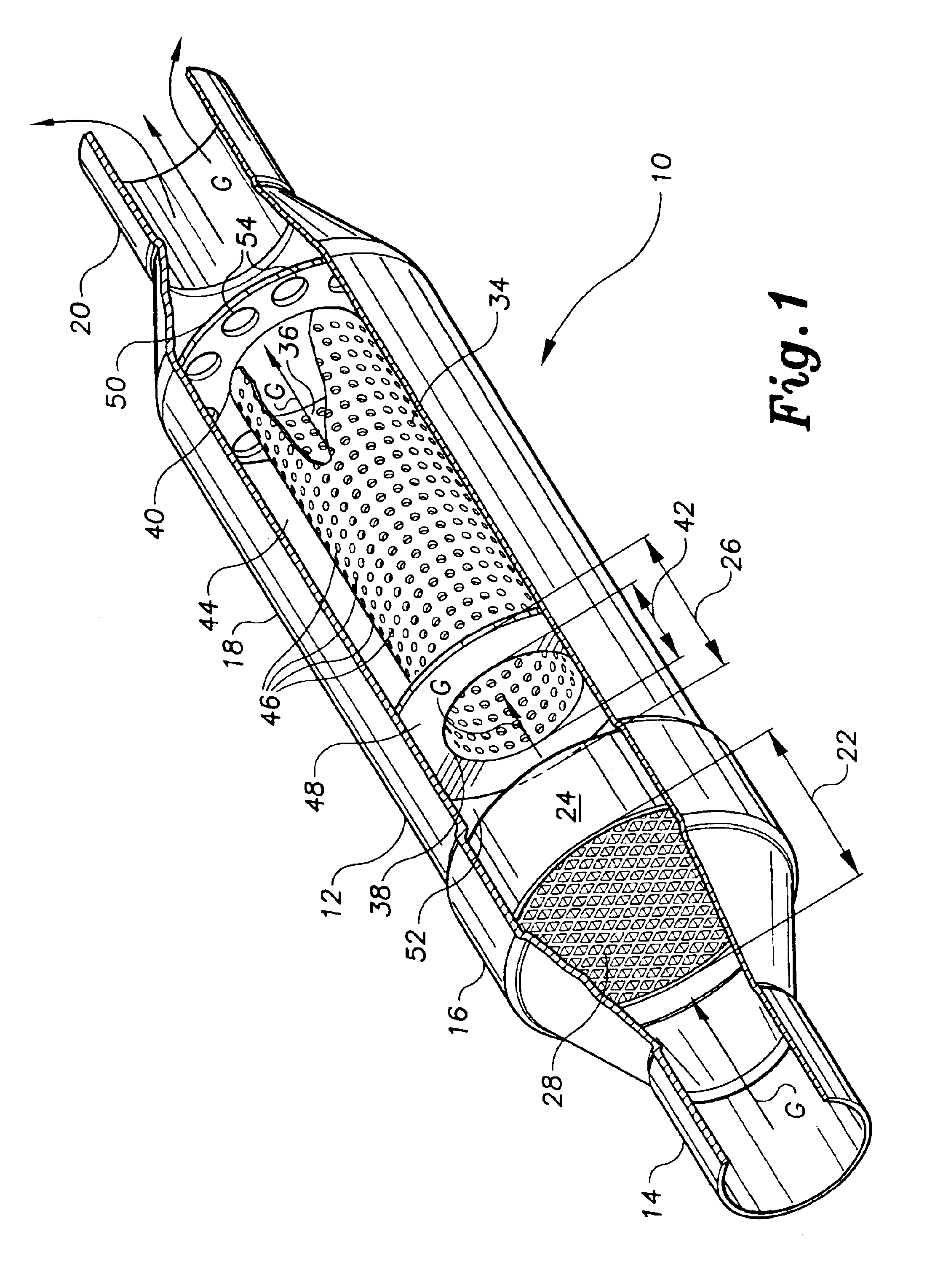
[0128]The forward resonator tube retaining plate 228 may be formed with a solid, impermeable periphery, as in the catalytic converter and resonator combination 10 of FIG. 1. However, an alternative is shown in the converter and resonator embodiment 200 of FIG. 4, in which both the front and rear plates 228 and 230 include a plurality of peripheral passages, respectively 236 and 238, therethrough, in the manner of the rear plate 50 of the converter and resonator combination 10 of FIG. 1, in order to allow any small amount of gases passing into the resonator plenum 232 to escape therefrom.

[0129]The catalytic converter and resonator combination 200 of FIG. 4 functions essentially like the converter and resonator 10 of FIG. 1, with exhaust gases G entering the canister 202 through the dual inlet pipes 212 of the inlet end 204, and thence passing through the single catalytic converter element 216. (While the single oval shaped converter element 216 is generally shaped to fit more convent...


PUM


Abstract

The exhaust sound and emission control system is a system for reducing sound and noxious emissions from an automotive exhaust. The system may have an exhaust resonator having one or more catalytic converter elements in combination therewith in a single device. Alternatively, the system may have multiple angularly disposed chambers therein, with a series of V-shaped baffles or guides in one of the chambers, thereby combining resonator and muffler functions in a single device. In another alternative, the system has a series of longitudinal tubes therein, in combination with a series of V-shaped guides or vanes, combining catalytic converter, muffler, and resonator functions in a single device. The various elements of the different embodiments, e.g. catalytic converter element(s), double wall shell, perforated tubes and multiple flow paths, interconnecting crossover tubes, etc., may be combined with one another as practicable.

Description

REFERENCE TO RELATED PATENT APPLICATIONS[0001]This application is a continuation-in-part of U.S. patent applications Ser. No. 09 / 135,804 filed on Aug. 18, 1998 and Ser. No. 10 / 252,506 filed on Sep. 24, 2002 now U.S. Pat. No. 6,651,733.BACKGROUND OF THE INVENTION[0002]1. Field of the Invention[0003]The present invention relates generally to automobile exhaust sound and emission control, including a catalytic exhaust converter and a resonator installed within the exhaust system for the reduction of exhaust noise, and to an exhaust sound attenuation and control system having multiple flow paths for reducing exhaust noise.[0004]2. Description of the Related Art[0005]By the time of the 1950s, it was becoming apparent that the ever-increasing volume of automobile and truck traffic was generating exhaust emissions which were adversely affecting the environment. This was particularly true in urban areas and other areas where geographic and meteorological conditions combined to create areas ...

Claims


Application Information

Patent Timeline
IPC IPC(8): F01N1/10F01N1/02F01N1/04F01N1/08F01N7/00F01N3/28F01N7/18F01N7/04F01N7/02F01N13/02F01N13/04F01N13/18
CPCF01N1/02F01N1/04F01N1/083F01N1/084F01N1/10F01N3/2885F01N13/04F01N13/18F01N13/1894F01N13/017F01N13/0097F01N13/0093F01N13/009F01N3/2828F01N2210/04F01N2230/04F01N2330/06F01N2330/34F01N2470/02F01N2470/14F01N2470/16F01N2490/155F01N2490/16
Inventor MAROCCO, GREGORY M.
Owner MAROCCO GREGORY M
Why Eureka
Try Eureka