Display device

a display device and display screen technology, applied in the direction of discharge tube/lamp details, discharge tube/lamp details, discharge tube with screen, etc., can solve the problems of insufficient orientation of luminance effect and insufficient luminance improvement

Active Publication Date: 2005-09-06
PANASONIC LIQUID CRYSTAL DISPLAY CO LTD +1
View PDF6 Cites 63 Cited by
  • Summary
  • Abstract
  • Description
  • Claims
  • Application Information

AI Technical Summary

Benefits of technology

[0020]The present invention is preferably applicable to various types of display devices and is particularly preferably applicable to a projection type cathode ray tube. Further, when the present invention is applied to a field emission type display device, in addition to the above-mentioned respective advantageous effects, it is possible to reduce damages on a phosphor screen (a phosphor film). Further, with respect to a heat cathode fluorescent lamp, a cold cathode fluorescent lamp and the like, the damages on the fluorescent film derived from the high-load excitation can be reduced and the extinction of light due to temperature can be enhanced.
, it is possible to reduce damages on a phosphor screen (a phosphor film). Further, with respect to a heat cathode fluorescent lamp, a cold cathode fluorescent lamp and the like, the damages on the fluorescent film derived from the high-load excitation can be reduced and the extinction of light due to temperature can be enhanced.

Problems solved by technology

In the above-mentioned non-patented literature, although the evaluation of a case in which ZnY2Si2O8 is used as a base material and Tb3+ green phosphor is used as an activating agent is disclosed, the luminance effect orientation is still insufficient.
Further, in the above-mentioned patent literature, although the luminance improvement effect due to rare earth ion is described, this luminance improvement effect is also insufficient.

Method used


Image

  • Display device
  • Display device
  • Display device

Examples


first embodiment

[First Embodiment]

[0031]As raw materials, 9.767 g of zinc oxide (ZnO), 21.000 g of yttrium oxide (Y2O3), 2.617 g of terbium oxide (Tb4O7) and 12.137 g of silicon oxide (SiO2) are prepared. These raw materials are sufficiently mixed. Then, to the mixture, an aqueous solution containing ytterbium ion (Yb3+) as rare earth ion is added at a plurality of given quantities described later using a measuring pipet in a state that a small quantity of ethanol is added to the mixture. The concentration of the aqueous solution containing ytterbium ion (Yb3+) is adjusted such that a quantity of ytterbium ion (Yb3+) becomes 10 mg / ml.

[0032]The mixture is dried in the air at a temperature of approximately 120° C. for one hour and, thereafter, is put into an alumina crucible and is subjected to heat treatment in the air at a temperature of 1400° C. for two hours. Here, an alumina-made lid is placed (without using an adhesive agent for ceramic) on the alumina crucible. The obtained product is transfer...

second embodiment

[Second Embodiment]

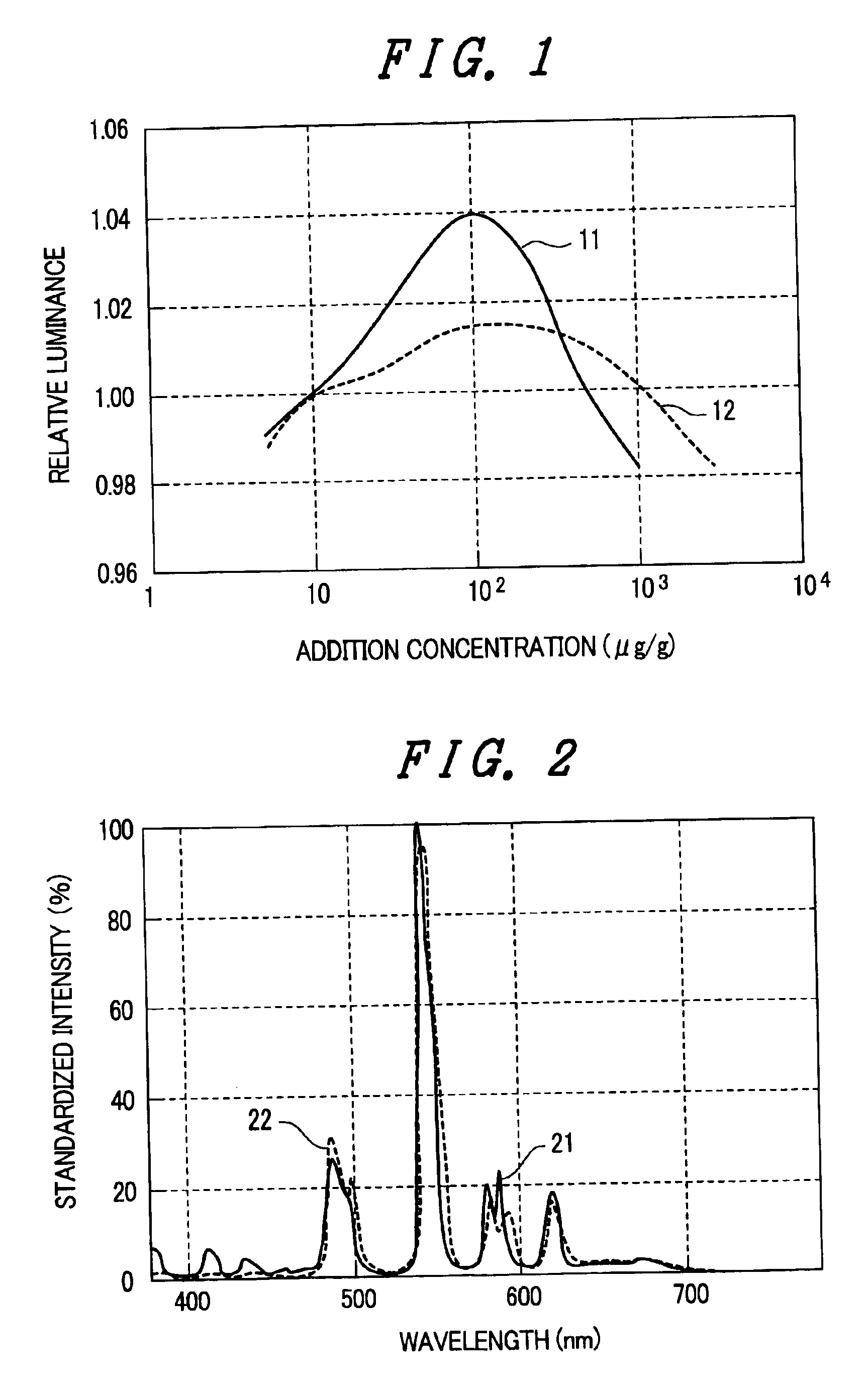
[0043]Next, the second embodiment of the present invention is explained. Using the same synthesizing method and conditions as the first embodiment, phosphors which are formed by adding samarium ion (Sm3+) as rare earth ion to the phosphor base material (ZnY2SiO8) are applied to a substrate and a plurality of test pieces are prepared. Then, the light emitting intensity is measured using the same evaluation method as that of the first embodiment. The relative values when the light emitting intensity output of the phosphor to which no rare earth ion (Sm3+) is added is 1 are shown in Table 2.

[0044]

TABLE 253000Sm content0(comparison(comparison(μg / g)(no additionexample)10501005001000example 4Relative10.9981.0001.0101.0351.0121.0000.981luminance

[0045]Further, the addition concentration dependency of the second embodiment of the present invention using samarium ion (Sm3+) as the rare earth ion is indicated in FIG. 1 by reference symbol 12. A temperature of test pieces (te...


PUM

PropertyMeasurementUnit
concentrationaaaaaaaaaa
temperatureaaaaaaaaaa

Abstract

The present invention can further enhance the light emission characteristics of phosphor excited by the irradiation of electron beams of high density. In a cathode ray tube including a phosphor film, a faceplate panel which constitutes a screen, an aluminum vapor-deposited film, a funnel and an electron gun, phosphor which constitutes the phosphor film applied to the faceplate panel is constituted of a terbium activated phosphor which is produced by substituting a portion of yttrium (Y) in base material crystals which contain zinc (Zn), yttrium (Y), silicon (Si) and oxygen (O) as main constitutional elements with terbium ion (Tb3+) and a trace amount of rare earth element ion is added to the terbium activated phosphor.

Description

BACKGROUND OF THE INVENTION[0001]1. Field of the Invention[0002]The present invention relates to a display device, and more particularly to a display device which enhances light emission characteristics of phosphor excited by the irradiation of electron beams having high density.[0003]2. Description of the Related Art[0004]With respect to a display device, various types of display devices have been known. Particularly, with respect to a projection type display device or a so-called projector, a cathode ray tube used in such a display device is required to exhibit high luminance and hence, phosphor which constitutes a screen of the display device is required to exhibit the excellent light emission characteristics upon excitation by electron beams at high density. Further, among display devices having a large screen, recently, a field emission display (FED) which constitute one of flat panel type cathode ray tubes has been developed. This FED is also required to include phosphor which...

Claims


Application Information

Patent Timeline
Patent Type & Authority Patents(United States)
IPC IPC(8): C09K11/77H01J1/63H01J1/00C09K11/79H01J29/20H01J31/10H01J31/12
CPCC09K11/7774H01J29/20C09K11/77742
Inventor MATSUKIYO, HIDETSUGUKASHIWAKURA, YASUHIDE
Owner PANASONIC LIQUID CRYSTAL DISPLAY CO LTD
Why Eureka
Try Eureka