

Structurally enhanced cracking catalysts
a structural enhancement and cracking technology, applied in the field of new materials, can solve the problems of blocking access and macroporosity not providing the results we have obtained, and achieve the effect of improving sodium removal characteristics and low sodium values
- Summary
- Abstract
- Description
- Claims
- Application Information
AI Technical Summary
Benefits of technology
Problems solved by technology
Method used
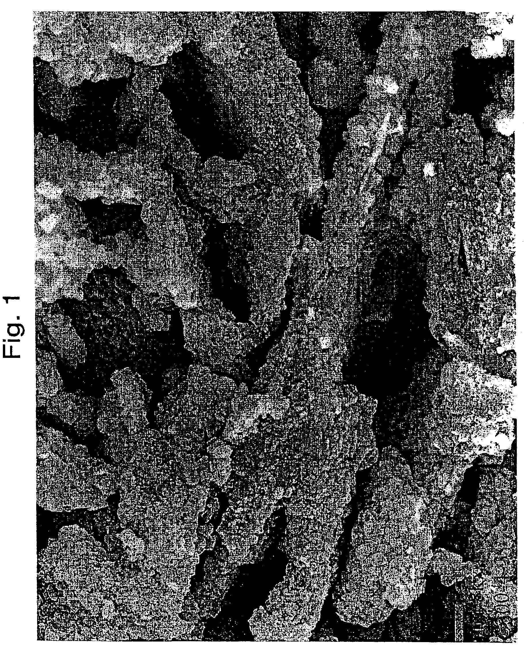
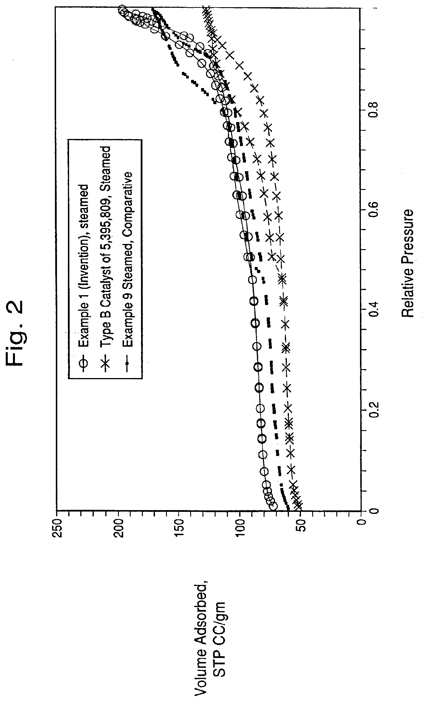
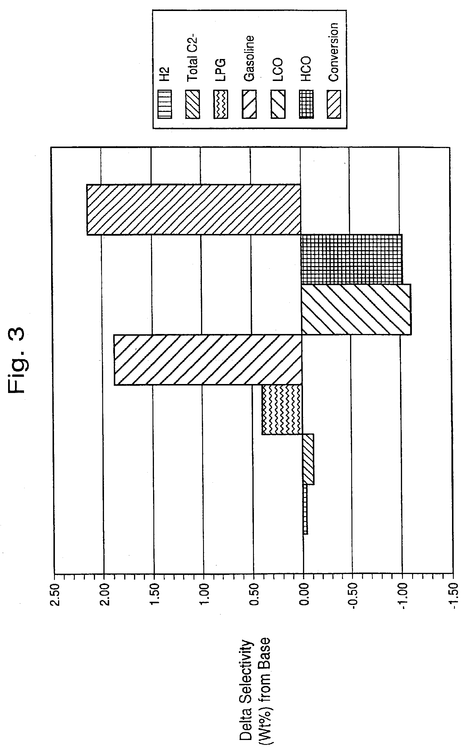
Image

Examples
example 1
[0070]A microsphere was prepared containing 30 parts of metakaolin (MK), 20 parts of wet media-milled Ansilex 93™, 20 parts of media-milled HiOpaque™ pigment calcined beyond 1,050° C., and 30 parts of NuSurf™ pigment which had been directly calcined beyond 1,050° C., pulverized and fluid-energy milled. To this mixture of calcined kaolins was added 15 parts of SiO2 added from N-brand® sodium silicate. This microsphere was not acid-neutralized. The metakaolin source was Metamax™, a pulverized powder, made down at 55% solids in tap water with 3 ml Colloid 211 surfactant (Viking Industries, Atlanta, Ga.) per kg of calcined kaolin. An air-driven Cowles mixer was used in a batch process where the dry kaolin was added to the water that already contained the surfactant. The kaolin was added more slowly to the water as the mixture thickened. A very dilatant slurry was formed but continued mixing reduced the viscosity. Gradual addition of the kaolin and continued mixing during 45 minutes or m...
example 2
[0077]A microsphere was prepared containing 30 parts of MK, 20 parts of wet media-milled Ansilex 93™ 20 parts of ball-milled NuSurf™ pigment calcined beyond 1,050° C., and 30 parts of NuSurf™ mullite aggregates prepared by pulverizing the hydrous pigment before calcining beyond 1,050° C., plus 15 parts of SiO2 added from N-brand® sodium silicate. This microsphere was acid-neutralized.
[0078]The MK source was a second batch of Metamax™ made down at 55% solids with C211 dispersant. The media-milled Ansilex 93™ was the same slurry as prepared in Example 1.
[0079]The ball-milled NuSurf™ mullite was prepared by calcining the hydrous delaminated pigment at 2350° F. for four hours in cordierite trays in a pre-heated furnace. This material was crushed, pulverized, and then wet ball milled at 46% solids. The final product was a low viscosity slurry with 90%<2 um by laser scattering.
[0080]The NuSurf™ mullite in this example was prepared to assure the formation of high pore volume aggregates wit...
example 3
[0085]A microsphere of exceptionally high pore volume and with unusually wide macropores was prepared with 30 parts of MK and 70 parts of NuSurf™ mullite aggregates; the latter prepared by pulverizing before calcining beyond 1,050° C. The calcined kaolin mixture was spray dried with 15 parts of SiO2 added from N-brand® sodium silicate. This microsphere was acid-neutralized.
[0086]The MK source was the same batch of Metamax™ made down in Example 2. The NuSurf™ mullite (aggregates) was also the same batch made down for Example 2. The two slurries were kept in suspension by rolling in sealed jugs until needed for blending.
[0087]The slurry for spray drying was formed by mixing the two component slurries in the 30:70 ratio on a 4.00 kg overall dry basis as noted above in a Cowles mixer. To this slurry 2.14 kg of N-brand® Sodium Silicate was added to form a mixture at 48% solids, which was sufficiently fluid to pump and spray dry. The material was spray dried using a 0.6 mm single fluid no...
PUM
| Property | Measurement | Unit |
|---|---|---|
| size | aaaaa | aaaaa |
| size | aaaaa | aaaaa |
| BET surface area | aaaaa | aaaaa |
Abstract
Description
Claims
Application Information