
Apparatus for measuring current density of fuel cell

a fuel cell and current density technology, applied in the direction of electrochemical generators, galvano-magnetic hall-effect devices, instruments, etc., can solve the problems of excessive humidification of the electrolyte membrane, laborious abnormality detection operation, and insufficient supply of reactant gases to the electrode surfaces, etc., to achieve the effect of simple structur

Inactive Publication Date: 2005-09-27
HONDA MOTOR CO LTD
View PDF4 Cites 10 Cited by
  • Summary
  • Abstract
  • Description
  • Claims
  • Application Information

AI Technical Summary

Benefits of technology

[0013]A main object of the present invention is to provide a current density measuring apparatus having a simple structure, in which current density distribution in the electrode surface can be obtained efficiency and reliably.
[0015]During power generation of the fuel cell, electric current flowing the fuel cell generates a magnetic field applied to the Hall elements. A detection signal indicating a voltage value (Hall voltage) is outputted from each of the Hall elements. The Hall voltage is proportional to the electric current during power generation. Based on the voltage values outputted from the Hall elements, current density distribution is determined efficiently and accurately. Thus, for example, flooding in the electrode surface can be detected reliably.

Problems solved by technology

During power generation, water produced in the chemical reaction is likely to be trapped on the outlet side of the reactant gas flow fields, and the electrolyte membrane may be humidified excessively.
If water flooding occurs, reactant gases may not be supplied to the electrode surfaces sufficiently.
In the technique of Japanese Laid-Open Patent Publication No. 8-222260, however, if there are many fuel gas grooves, since it is necessary to insert the stainless thin tube in each of the fuel gas grooves for measuring hydrogen concentration, the abnormality detecting operation is laborious, and time consuming.
Thus, it takes considerable time to measure density of electric current in the electrode surface during power generation.
The abnormality detecting operation can not be performed efficiently.

Method used


Image

  • Apparatus for measuring current density of fuel cell
  • Apparatus for measuring current density of fuel cell
  • Apparatus for measuring current density of fuel cell

Examples


Embodiment Construction

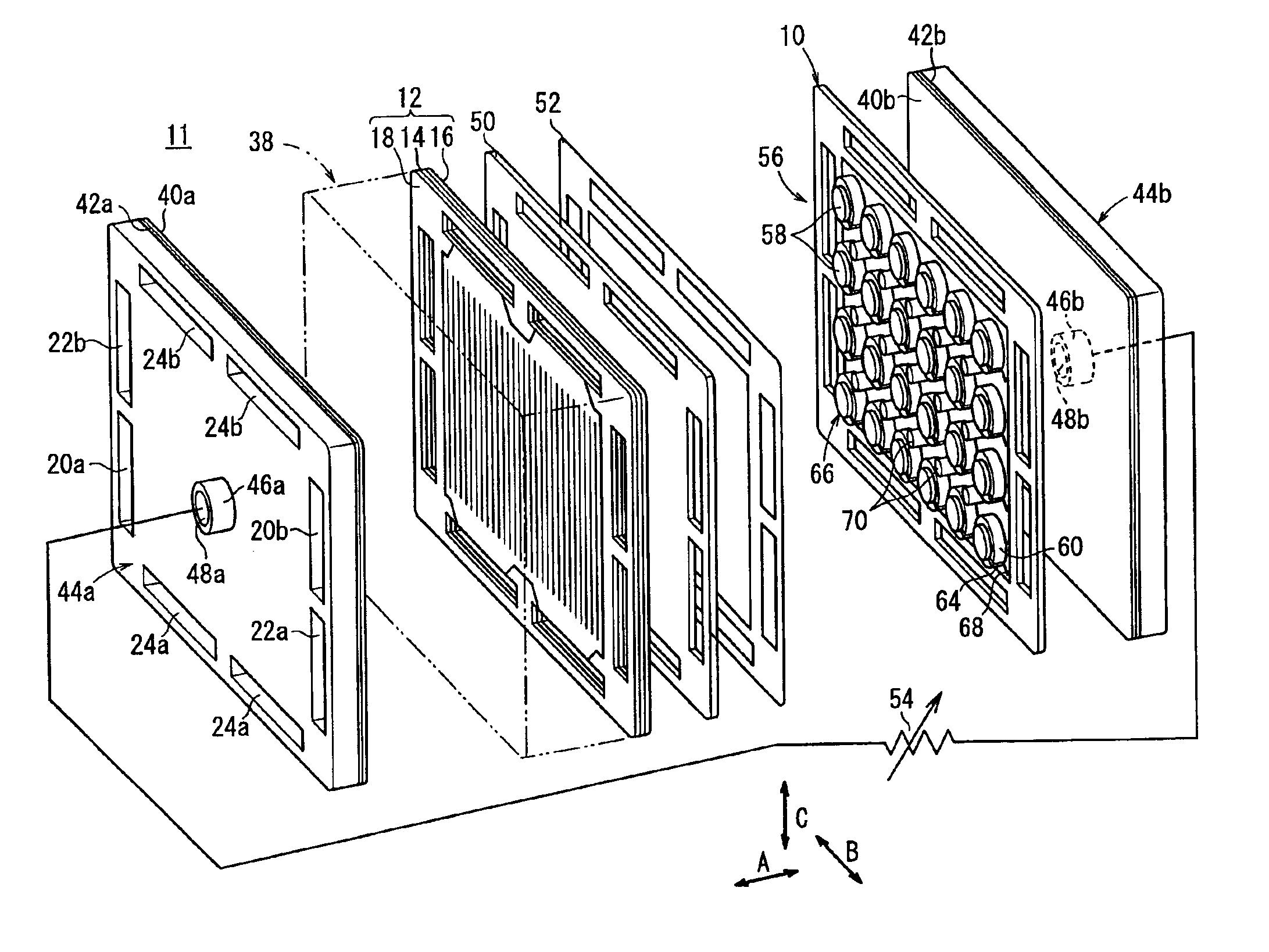
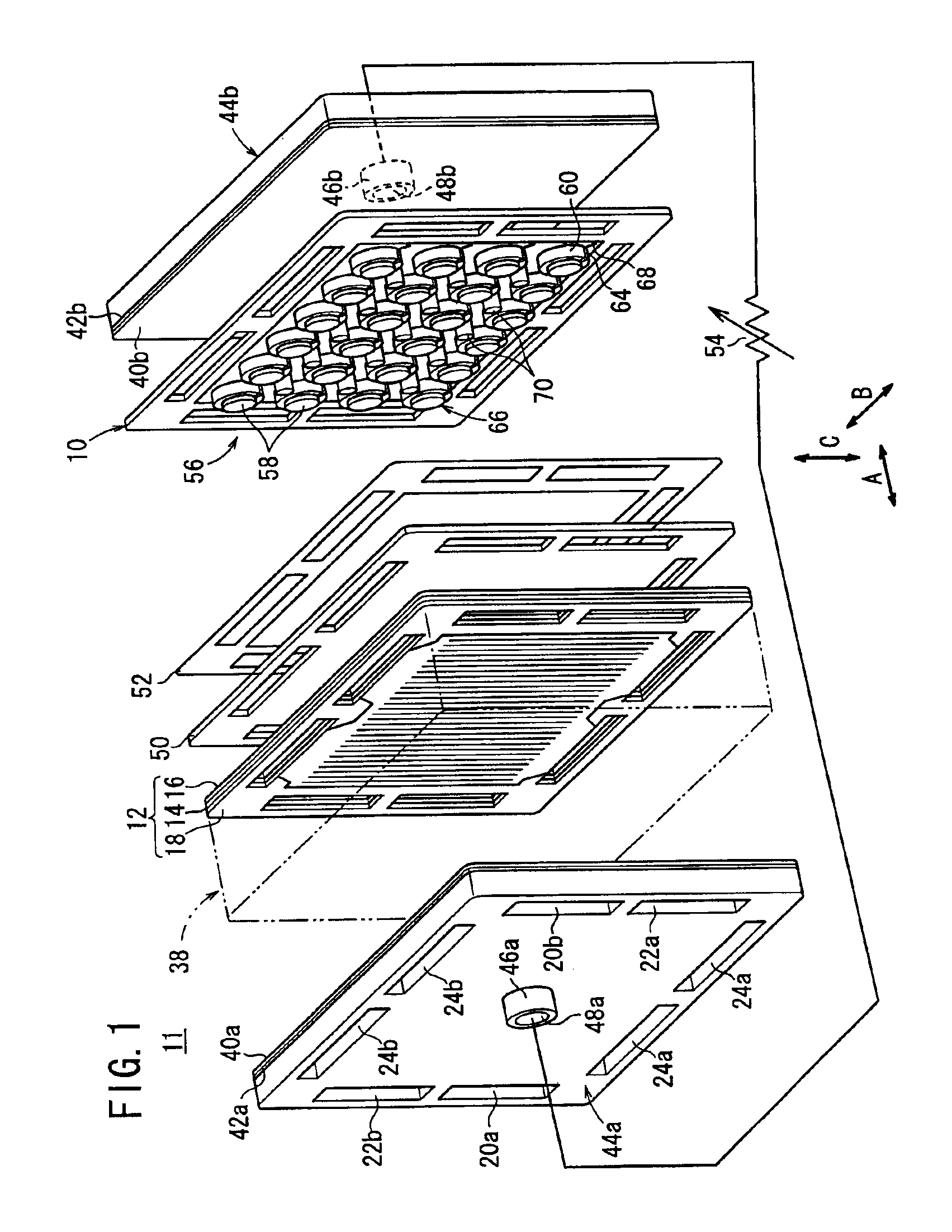
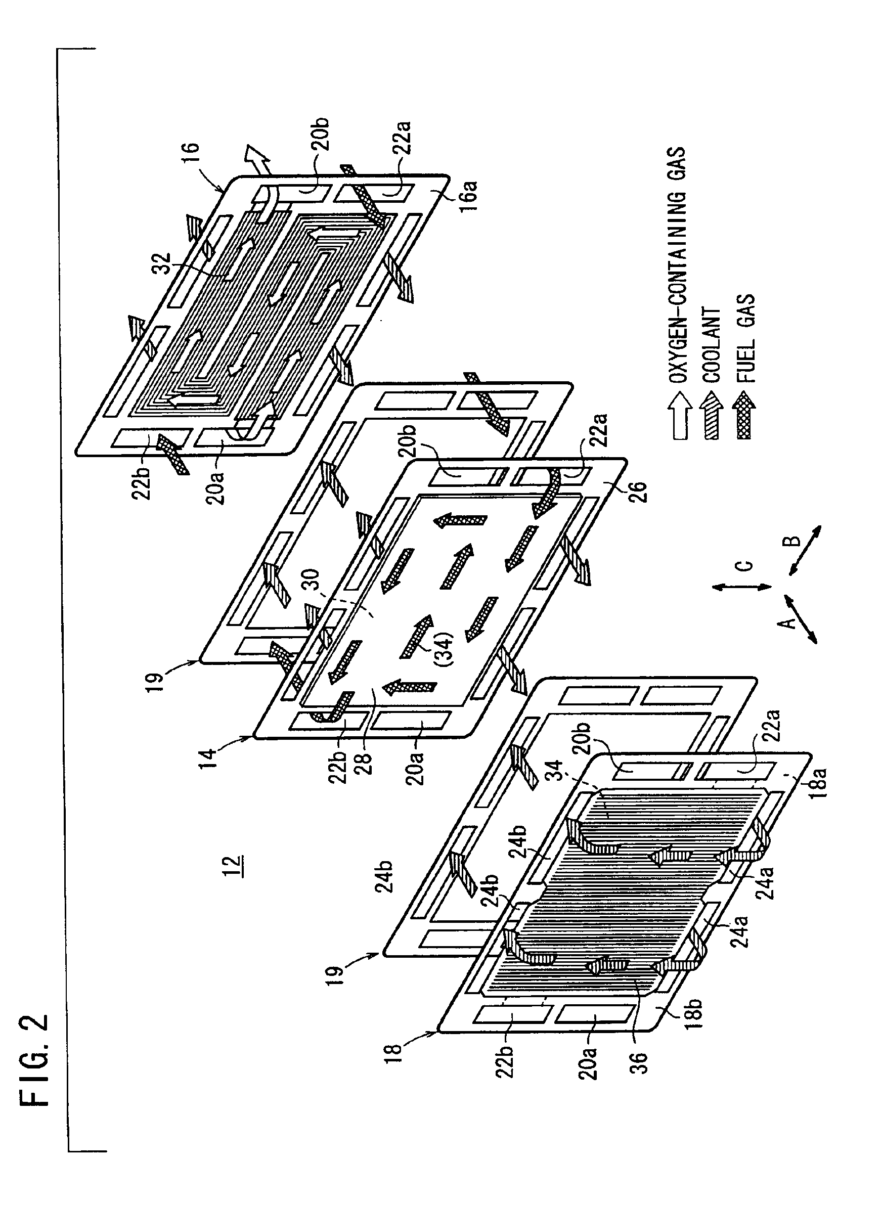
[0025]FIG. 1 is an exploded perspective view showing main components of a fuel cell system 11 including an apparatus for measuring current density (current density measuring apparatus) 10 according to an embodiment of the present invention. The current density measuring apparatus 10 measures current density of a fuel cell 12. FIG. 2 is an exploded perspective view showing main components of the fuel cell 12.

[0026]As shown in FIG. 2, the fuel cell 12 includes a membrane electrode assembly (electrolyte electrode assembly) 14, and first and second separators 16, 18 for sandwiching the membrane electrode assembly 14. Seal members 19 such as a gasket are provided between the membrane electrode assembly 14, and the first and second separators 24, 26 for sealing passages as described later and electrode surfaces (power generating surfaces).

[0027]At one end of the fuel cell 12 in a direction indicated by an arrow B, an oxygen-containing gas supply passage 20a for supplying an oxygen-contain...


PUM

PropertyMeasurementUnit
current densityaaaaaaaaaa
voltageaaaaaaaaaa
current density measuringaaaaaaaaaa

Abstract

A fuel cell system includes a fuel cell. A current density measuring apparatus is provided on a cathode side of the fuel cell. The current density measuring apparatus includes a plurality of Hall elements provided at positions corresponding to measuring positions in an electrode surface. Each of the Hall element is attached to a ferrite core fitted to a pole of a sensor mounting plate. The ferrite core and the Hall element attached to the pole make up a current sensor.

Description

BACKGROUND OF THE INVENTION[0001]1. Field of the Invention[0002]The present invention relates to an apparatus for measuring current density of a fuel cell. The fuel cell includes an electrolyte electrode assembly, and separators for sandwiching the electrolyte electrode assembly. Each of the electrolyte electrode assemblies includes a pair of electrodes and an electrolyte interposed between the electrodes.[0003]2. Description of the Related Art[0004]For example, a solid polymer electrolyte fuel cell employs a membrane electrode assembly (MEA) which comprises two electrodes (anode and cathode) and an electrolyte membrane interposed between the electrodes. The electrolyte membrane is a polymer ion exchange membrane (proton exchange membrane). The membrane electrode assembly is interposed between separators. The membrane electrode assembly and the separators make up a unit of a fuel cell (unit cell) for generating electricity. Typically, a predetermined number of membrane electrode ass...

Claims


Application Information

Patent Timeline
Patent Type & Authority Patents(United States)
IPC IPC(8): G01R19/08G01R31/36H01L43/04H01L43/06H01M8/04H01M8/10
CPCG01R19/08G01R31/3606G01R31/382H01M8/04552H01M8/04582Y02E60/50
Inventor MOHRI, MASAHIROFUJII, YOSUKEHAYASHI, KATSUMIWAKAHOI, TOSHIYA
Owner HONDA MOTOR CO LTD
Learn More