Electroacoustic transducer with field replaceable diaphragm carrying two interlaced coils, without manipulating any wires

a field-replaceable diaphragm and transducer technology, applied in the direction of electrical transducers, transducer casings/cabinets/supports, electrical apparatus, etc., can solve the problems of not having the same popularity, not having a uniform sound emitting activity on the surface of cones or domes, and the demands of audio signals can be so great, so as to achieve easy field replacement and simple operation

Inactive Publication Date: 2005-10-18
MAZARAKIS ANTHONY
View PDF5 Cites 19 Cited by
  • Summary
  • Abstract
  • Description
  • Claims
  • Application Information

AI Technical Summary

Benefits of technology

[0012]A primary object of the present invention is to provide a planar sound reproducer with excellent performance characteristics, the values of which are secured, and maintained at all times by offering the following features:
[0014](B) An easy and simple way of replacing the diaphragm, by the user, in the field, without the need to manipulate any wires and soldering tools in case of failure, or, in case of installing diaphragm with different characteristics.
[0017]In the present invention the replacement of the diaphragm is accomplished by the user in a very simple operation, without the need of manipulating wires or using a soldering or de-soldering means, as is necessary in prior art equipment.
[0018]In the prior art, the diaphragm of commercial planar speakers employ for driving, single coil, in contrast, with the present invention which provides two (binary) interlaced coil, for simultaneous driving. In the present invention, in addition to the easy field replacement, the diaphragm is characterized by two symmetrical coils configuration, which are interlaced, in a manner of being the one into each other, thus occupying the same area of the said diaphragm and securing the fact that the two coils are absolutely identical with all electrical characteristics such as Resistance, Impedance, Inductance being absolutely equal. Such Binary Interlaced Coils can be laid, in a multiplicity of similar B.I.C. executions, on the same long diaphragm tensioning adjustment means, for obtaining desired low frequency operation. A long and slim loudspeaker embodying in its diaphragm a multiplicity of binary interlace coils, can lead to the design of full range hybrid speaker driver, with line source behavior. The two coils in the present invention are characterized by symmetricity and equality of their parameters, a condition which permit the creation of several combinations of impedance networks, which can act as the output loads of an amplifier.

Problems solved by technology

Such transducers, which are called Planar Loudspeakers or some times Ribbon Loudspeakers, in the past years have not enjoyed the same popularity as the cone-type speakers—in spite of the superior performance of the diaphragmatic types—due primarily their high cost, and the different performance characteristics.
As is known to those skilled in the art of sound reproduction, the “pistonic” operation of cones or domes is not at all secured throughout their operating range, and as a result there may not be a uniform sound emitting activity from the surface of the cone or dome.
The demands of the audio signal can be so great in terms of moving speed and acceleration that the inertial masses or weights of the vibrating parts is a significantly limiting factor.
As a result the reproduced waveform is greatly affected especially in high frequencies where the relative inertias cannot be met by the electromagnetic motor moving the heavy cones or domes.
The disappointment of the user may arise, however, if the delicate vibrating diaphragm happens to fail, either by mechanical failure or by thermal failure of the coil.
In such situation, the remainder of the expensive structure of the planar loudspeaker is wasted as it is essentially rendered inoperative.
Invariably such planar Loudspeaker failures are not remediable by the user.
Under those circumstances the magnetic structure and in fact the entire loudspeaker, for which the audiophile has paid dearly, becomes a total loss or waste.

Method used


Image

  • Electroacoustic transducer with field replaceable diaphragm carrying two interlaced coils, without manipulating any wires
  • Electroacoustic transducer with field replaceable diaphragm carrying two interlaced coils, without manipulating any wires
  • Electroacoustic transducer with field replaceable diaphragm carrying two interlaced coils, without manipulating any wires

Examples


first embodiment

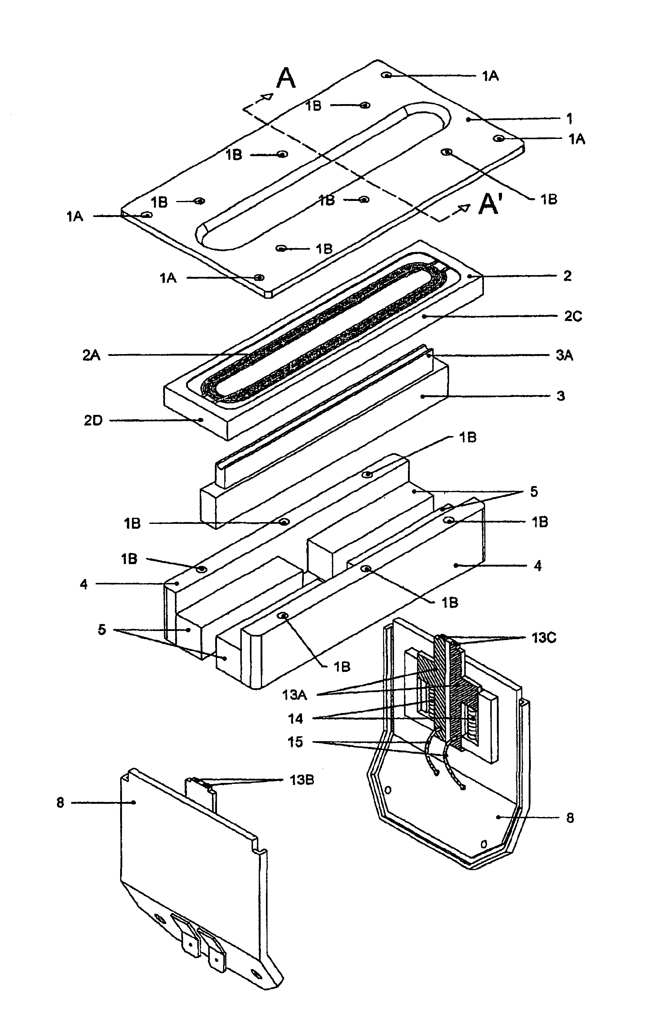
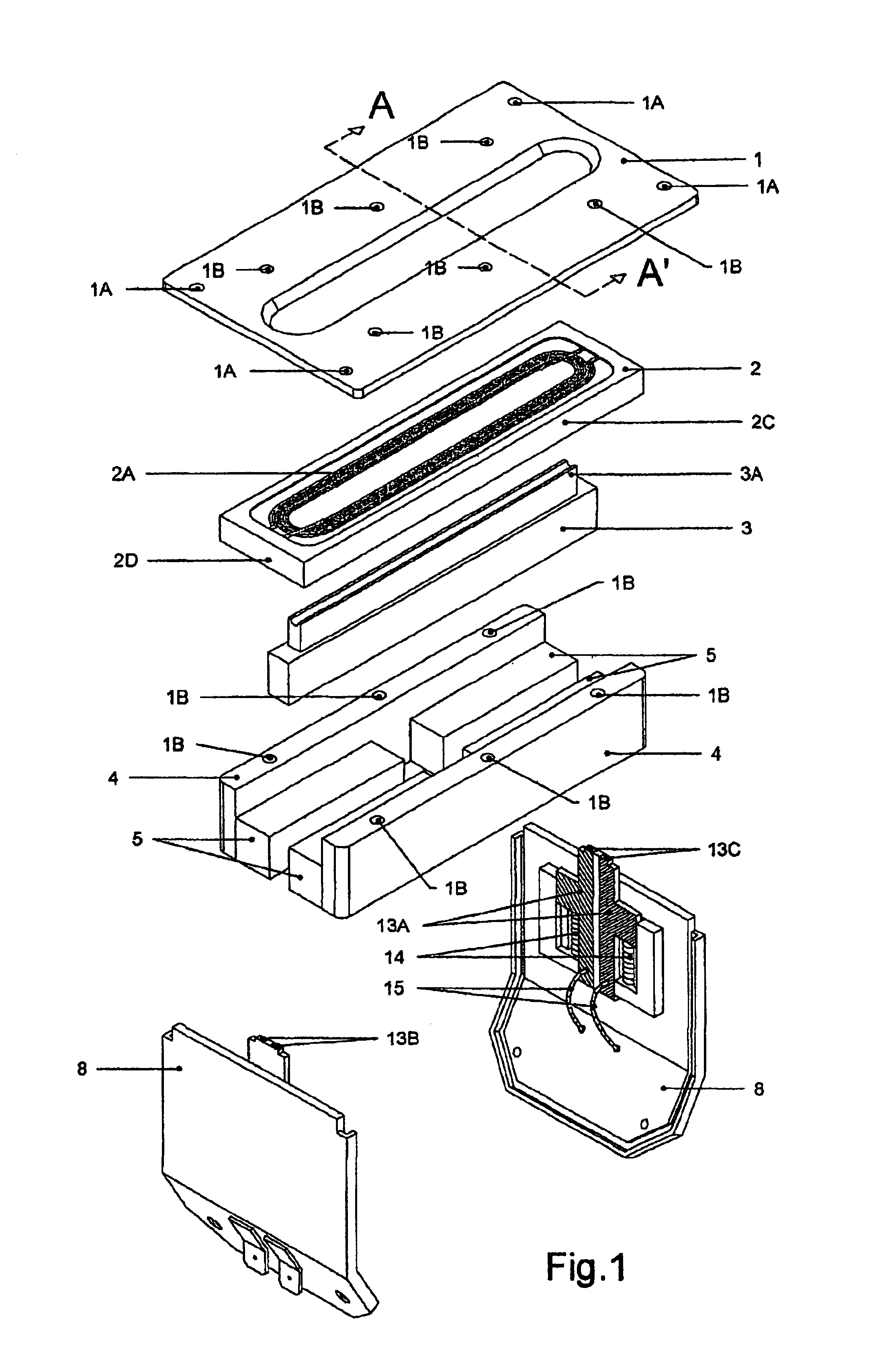
[0059]FIG. 1 An exploded view illustrating the components of the Planar Loudspeaker at its first embodiment of the Present invention.

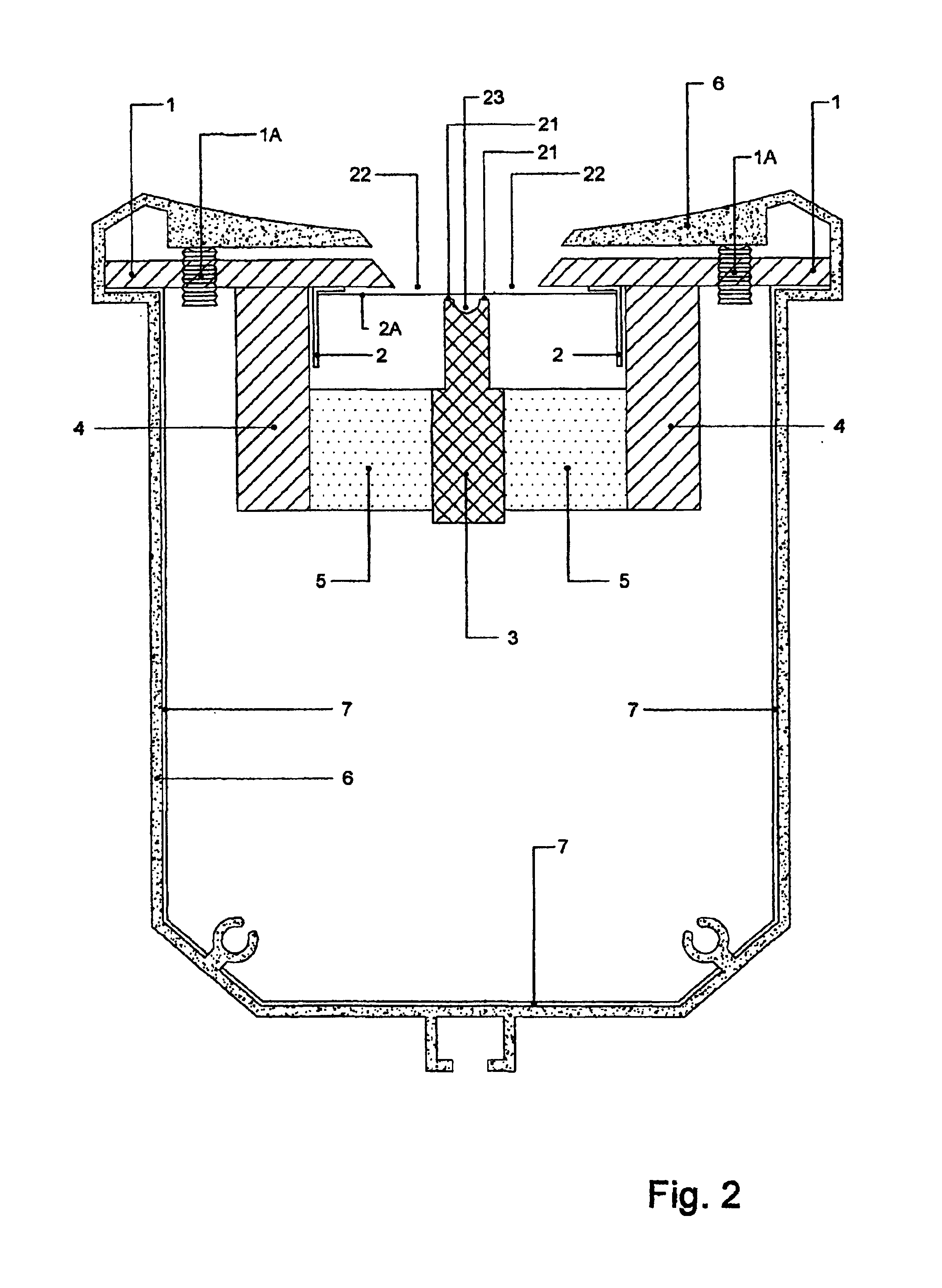
[0060]FIG. 2 Sectional view taken through cut line A-A′ of FIG. 1 with the Planar loudspeaker components, being in the assembled Position, and installed in the aluminum enclosure.

[0061]FIG. 2A Perspective view of the complete planar loudspeaker assembled in the aluminum enclosure and the two covers in position.

[0062]FIG. 2B A fragmentary enlarged view of upper plate and aluminum enclosure showing the way of fixing in place the complete transducer inside the aluminum enclosure

second embodiment

[0063]FIG. 3 Top view of the exchangeable diaphragm assembly, showing the present inventions the binary interlaced coils 1 and 2.

third embodiment

[0064]FIG. 4 Perspective view of a third embodiment showing the contact island and the spring loaded mating contacts approaching.

[0065]FIG. 5 A fragmentary enlarged view of a portion of the diaphragm's conductor, being exposed in the influence of magnetic Field in the air gap and the unidirectional forces, acting to all portions of the coil


PUM


Abstract

The present invention is directed to a diaphragmatic (planar) electroacoustic transducer that forms a complete sound radiating transducer and provides high efficiency and linearity. The diaphragm is easily exchangeable and rectangular in shape, and may be made of very thin polyamide film with a plurality of aluminum conductors formed on one side of the diaphragm. The plurality of conductors form two identical and symmetrical coils such that conductors of each coil are interlaced. The two sections of the coils are disposed in dense air-gaps of the magnet system, which comprises a plurality of high (BHmax) Neodymium magnets. The binary interlaced coils can be utilized in a number of modes, for the purpose of accomplishing a variety of operating modes.

Description

TECHNICAL FIELD OF THE INVENTION[0001]This invention relates to electroacoustic transducers which act as Loudspeakers and, in particular, to the thin diaphragm type of Audio transducers, which convert electrical (audio) energy into movement of a sound emitting diaphragm.BACKGROUND OF THE INVENTION[0002]Such transducers, which are called Planar Loudspeakers or some times Ribbon Loudspeakers, in the past years have not enjoyed the same popularity as the cone-type speakers—in spite of the superior performance of the diaphragmatic types—due primarily their high cost, and the different performance characteristics.[0003]The conventional, cone or dome Loudspeakers are known as electromagnetic motor actuated point sound source emitting devices.[0004]As is known to those skilled in the art of sound reproduction, the “pistonic” operation of cones or domes is not at all secured throughout their operating range, and as a result there may not be a uniform sound emitting activity from the surface...

Claims


Application Information

Patent Timeline
Patent Type & Authority Patents(United States)
IPC IPC(8): H04R9/04H04R9/00H04R7/00H04R7/18
CPCH04R7/00H04R9/04H04R7/18
Inventor MAZARAKIS, ANTHONY
Owner MAZARAKIS ANTHONY
Why Eureka
Try Eureka