Method of determining dose uniformity of a scanning ion implanter

Inactive Publication Date: 2005-11-15
APPLIED MATERIALS INC
View PDF14 Cites 81 Cited by
  • Summary
  • Abstract
  • Description
  • Claims
  • Application Information

AI Technical Summary

Benefits of technology

[0014]It is an object of embodiments of the present invention to enable improved monitoring of the ion beam current during ion implant

Problems solved by technology

Unfortunately, the current of desired ions delivered to the wafer in the beam of a typical implanter is not completely constant.
The beam current may experience relatively slow drift, and additionally may experience sudden and short term changes.
However, it has proved impracticable to make a continuous and reliable current reading of beam ions impinging on the substrate during the implant process, so that in practice only those ions which bypass the substrate during the scanning procedure can be effectively monitored with a faraday collector located behind the substrate holder.
An additional problem with obtaining an accurate measure of beam current during the ion implantation process is that the faraday collector used to monitor beam current can only detect and respond to charged particles in the beam.
However, the presence of neutralised particles in the ion beam does present a problem for obtaining accurate measurements of beam current, since neutral particles will not be measured.
However, the implantation process on a su

Method used


Image

  • Method of determining dose uniformity of a scanning ion implanter
  • Method of determining dose uniformity of a scanning ion implanter
  • Method of determining dose uniformity of a scanning ion implanter

Examples


Embodiment Construction

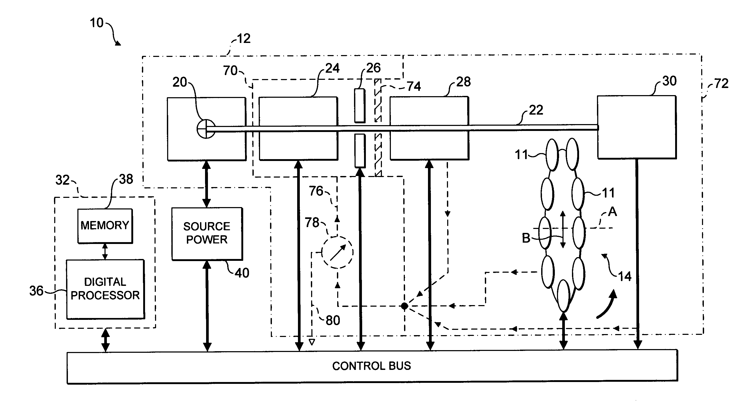
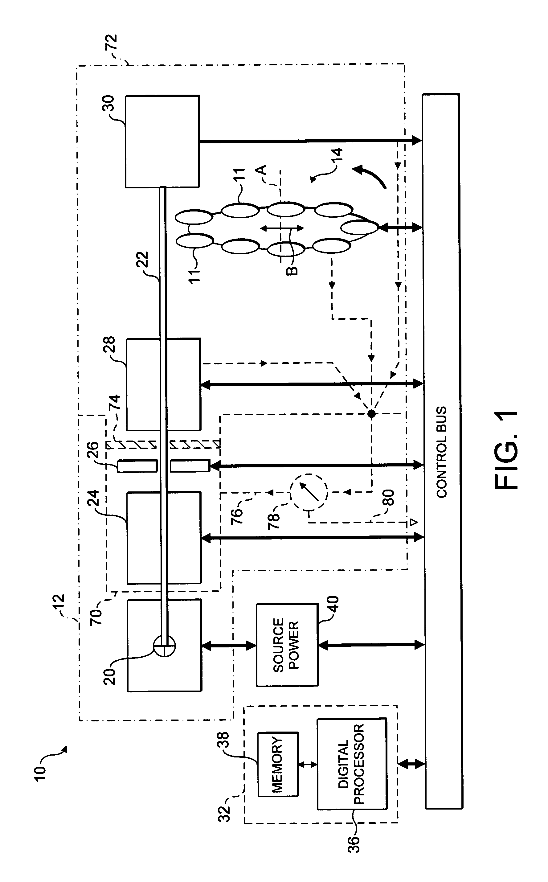
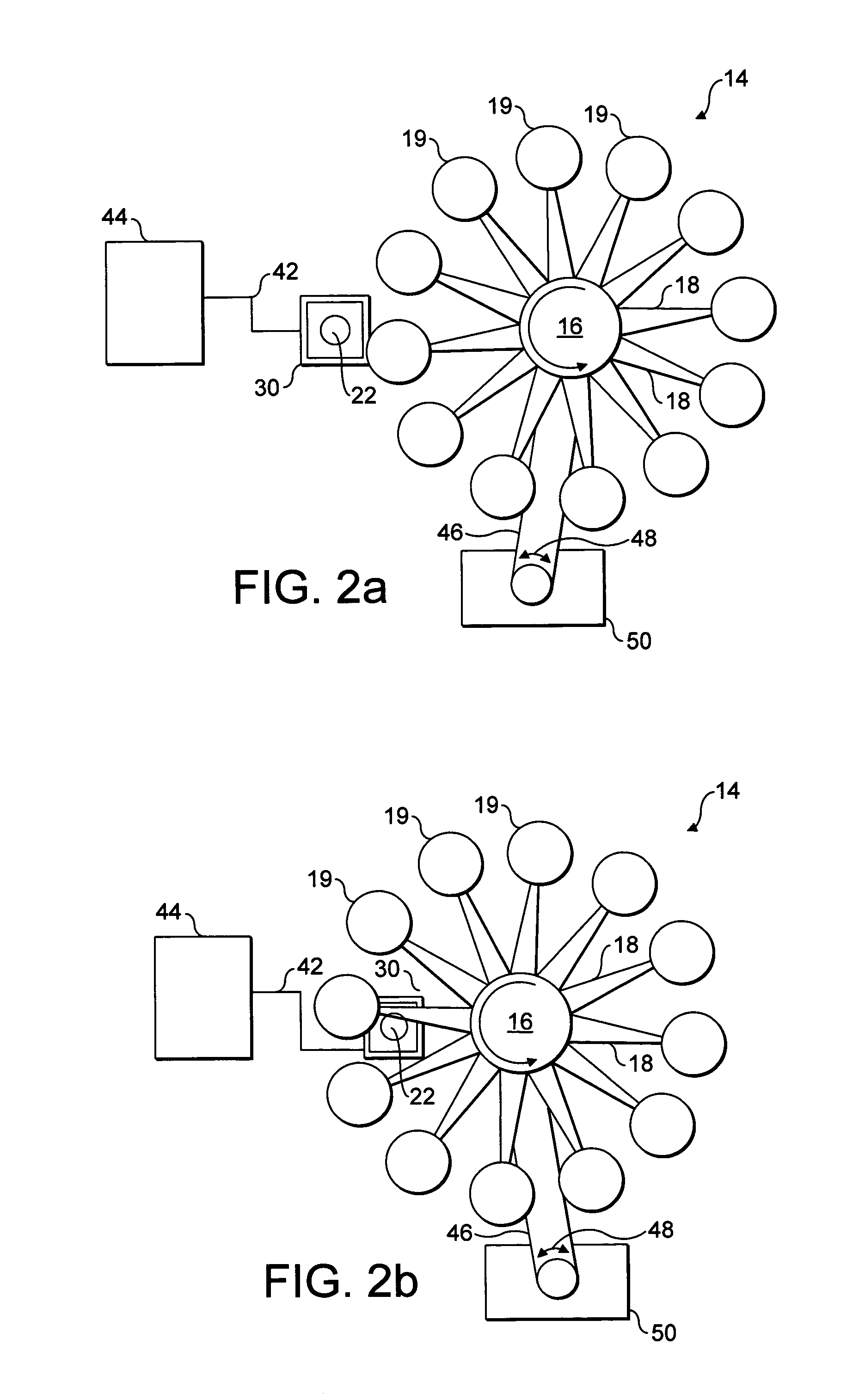
[0038]Referring to FIG. 1, the present invention may be embodied as a batch type ion implanter 10 of the type in which a plurality of substrate wafers 11 are mounted in a vacuum chamber, indicated generally at 12, around the periphery of a spoked type scan wheel 14 (shown only schematically in FIG. 1, but in more detail in FIG. 2). As seen in FIG. 2, the scan wheel 14 comprises a hub 16 having radially extending spokes 18 supporting substrate holders 19 equally spaced about the periphery of the wheel. In operation, the wheel 14 is rotated about an axis A and simultaneously the axis A is reciprocated as indicated by arrows B.

[0039]The ion implanter 10 further comprises within the vacuum chamber 12 an ion source 20 generating a beam of ions directed into a magnetic analyser 24. The analyser 24 typically comprises a magnetic sector which causes ions passing through the magnetic field to adopt paths having a curvature dependent on their mass / charge ratio. The ion beam is shown passing t...


PUM


Abstract

Dose uniformity of a scanning ion implanter is determined. A base beam current is measured at the beginning and/or the end of a complete scan over the whole substrate area. This base beam current is measured at a time when the measurement should be unaffected by outgassing from a substrate being implanted and a base dose distribution map is then calculated for the scan in question. During the scan itself beam instability events are detected and the magnitude and position in the scan of the detected instability events is measured. Corresponding deviations in the calculated base dose map are determined and subtracted from the previously calculated base dose distribution map to provide a corrected distribution map. By determining overall dose uniformity substractively in this way, good overall accuracy can be obtained with lesser accuracy in the measurement of the beam instability events.

Description

FIELD OF THE INVENTION[0001]This invention is concerned with ion implanters and in particular with methods for determining ion dose uniformity over a substrate being implanted by such implanters.BACKGROUND OF THE INVENTION[0002]Ion implanters are used to modify semiconductor substrate material by implanting ions of a desired species into the substrate, thereby altering the properties of the substrate.[0003]Ion implantation takes place in a vacuum chamber, in which a substrate or wafer, into which ions are to be implanted, is mounted on a holder. Ions are usually directed from an ion source towards the substrate in the form of a beam, and the beam cross-sectional area is usually smaller than the wafer to be implanted. In order to implant evenly over the entire surface of the substrate wafer, some relative scanning between the substrate and the beam is provided.[0004]Various scanning arrangements have been proposed and used in the prior art, including two-dimensional beam scanning wit...

Claims


Application Information

Patent Timeline
IPC IPC(8): H01J37/256H01J37/252H01J37/317
CPCH01J37/3171H01J2237/31703Y10S438/961H01J37/244H01J37/304H01J37/252H01J37/30H01J37/317
Inventor WAGNER, DENNIS W.GALLO, BIAGIOKINDERSLEY, PETER TORINABERLE, DAVID EUGENESIMMONS, JONATHON YANCEY
Owner APPLIED MATERIALS INC
Why Eureka
Try Eureka