High speed radiographic imaging assembly

a radiographic and assembly technology, applied in the field of radiography, can solve the problems of poor image quality, poor resolution, and inability to use higher-speed films in such assemblies, and achieve the effects of high system photographic speed, high contrast, and sharp images

Inactive Publication Date: 2005-11-22
CARESTREAM HEALTH INC
View PDF29 Cites 2 Cited by
  • Summary
  • Abstract
  • Description
  • Claims
  • Application Information

AI Technical Summary

Benefits of technology

[0020]In particular, the present invention provides high contrast and very sharp images using an imaging assembly that has very high system photographic speed (at least 700, preferably at least 1100, and more preferably at least 1400). The imaging assembly can be particularly useful for pediatric radiography or other instances where it is particularly necessary to limit patient exposure to X-radiation.
[0021]In addition, all other desirable sensitometric properties are maintained and the radiographic film of the imaging assembly can be rapidly processed in conventional processing equipment and compositions.
[0022]These advantages are achieved by using a novel combination of a high speed symmetric radiographic silver halide film (at least 400 film speed) and a pair of high speed fluorescent intensifying screens (at least 400 screen speed) arranged on opposing sides of the film. The symmetric radiographic silver halide film preferably has unique silver halide emulsion layers comprising tabular silver halide grains having specific halide compositions, grain sizes, and aspect ratios to achieve the desired film speed. In more preferred embodiments, the tabular grains in all emulsion layers are dispersed in a hydrophilic polymeric vehicle mixture that includes at least 0.05 weight % of oxidized gelatin (based on total dry weight of the hydrophilic polymeric vehicle mixture). With the unique choice of fluorescent intensifying screen and radiographic film of this invention, images with increased sharpness can be obtained at high speeds (thus, at lower radiation dosage). Such image quality improvements can be characterized by screen SSM values being greater than the values represented by reference Curve A of FIG. 4 over the range of spatial frequencies. In some preferred embodiments, image quality improvements can be characterized by screen SSM values being greater than the values represented by reference Curve A of FIG. 5 over the range of spatial frequencies.
[0023]Further advantages are provided in preferred embodiments with a specific microvoided reflective substrate in the flexible support of the fluorescent intensifying screen used in the imaging assembly. Within the microvoids are suitable reflective inorganic particles, and especially particles of barium sulfate. As a result, this screen has increased reflectivity to electromagnetic radiation, especially radiation in the region of from about 350 to about 450 nm.

Problems solved by technology

Thus, imaging assemblies that can be used with low radiation dosages (that is, “high speed” assemblies) generally provide images with poorer image quality (poorer resolution).
The use of higher speed films in such assemblies may not be useful because of higher fog or unwanted density in the non-imaged areas of the film, or loss in sharpness or resolution.

Method used


Image

  • High speed radiographic imaging assembly
  • High speed radiographic imaging assembly
  • High speed radiographic imaging assembly

Examples


example 1

[0130]Radiographic Film A:

[0131]Radiographic Film A was a duplitized film having the two different silver halide emulsion layers on each side of a blue-tinted 170 μm transparent poly(ethylene terephthalate) film support and an interlayer and overcoat layer over each emulsion layer. The emulsions of Film A were not prepared using oxidized gelatin.

[0132]Radiographic Film A had the following layer arrangement:[0133]Overcoat[0134]Interlayer[0135]Emulsion Layer[0136]Support[0137]Emulsion Layer[0138]Interlayer[0139]Overcoat

[0140]The noted layers were prepared from the following formulations.

[0141]

Coverage (mg / dm2)Overcoat FormulationGelatin vehicle 3.4Methyl methacrylate matte beads 0.14Carboxymethyl casein 0.57Colloidal silica (LUDOX AM) 0.57Polyacrylamide 0.57Chrome alum 0.025Resorcinol 0.058Spermafol 0.15Interlayer FormulationGelatin vehicle 3.4Carboxymethyl casein 0.57Colloidal silica (LUDOX AM) 0.57Polyacrylamide 0.57Chrome alum 0.025Resorcinol 0.058Nitron 0.044Emulsion Layer Formula...

example 2

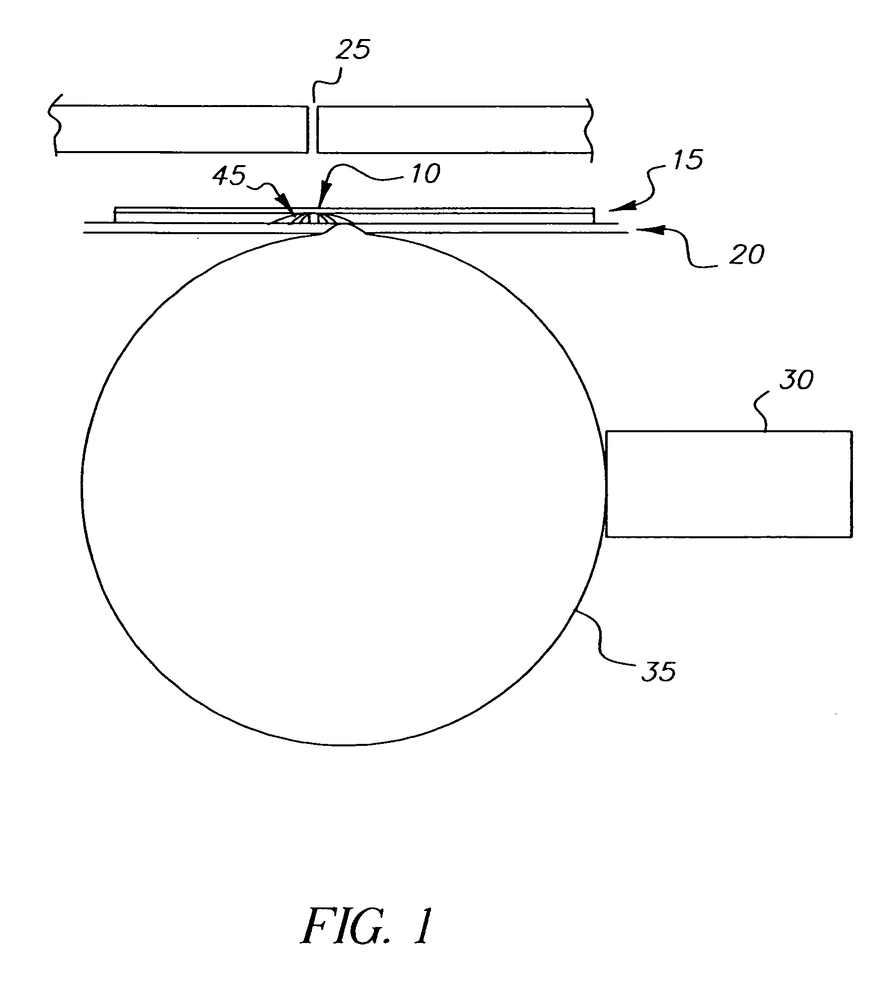
[0165]Cassettes used for imaging contained a pair of screens X, Y, or V, on opposing sides of the noted Radiographic Films A, B, or C described in Example 1.

[0166]Fluorescent intensifying screen “V” was a fluorescent intensifying screen that comprised a terbium activated gadolinium oxysulfide phosphor (median particle size of 7.8 to 8 μm) dispersed in a Permuthane™ polyurethane binder in a single phosphor layer on a microvoided poly(ethylene terephthalate) support. The total phosphor coverage was 9.2 g / dm2 and the phosphor to binder weight ratio was 27:1. The screen speed was 600.

[0167]The microvoided support used in Screen V was prepared as a 3-layer film (with designated layers 1, 2 and 3) comprising voided polyester matrix layers. Materials used in the preparation of layers 1 and 3 of the film were a compounded blend consisting of 60% by weight of barium sulfate (BaSO4) particles approximately 0.7 μm in diameter (Blanc Fixe XR-HN available from Sachtleben Corp.) and 40% by weight...

example 3

[0176]Radiographic Film C described above in Example 1 can also be combined with pairs of the fluorescent intensifying screens shown in TABLE V. Those imaging assemblies having system speeds of at least 700 are within the scope of the present invention.

[0177]

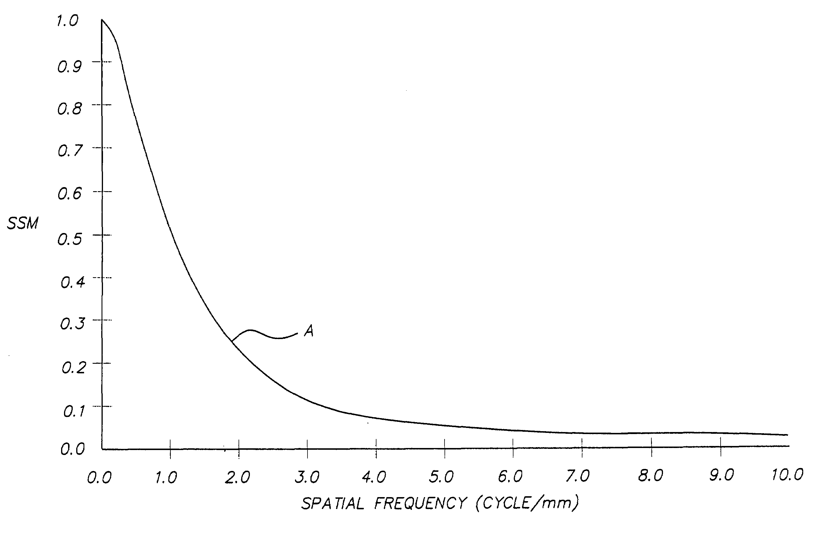
ScreenSystemSSM @ 2FilmScreenSpeedSpeedcycles / mmCKODAK1003000.83Lanex ® FineCKODAK1805000.79InSight ®SkeletalMediumCKODAK2807000.49(Invention)Lanex ®Medium

[0178]The invention has been described in detail with particular reference to preferred embodiments thereof, but it will be understood that variations and modifications can be effected within the spirit and scope of the invention.


PUM

PropertyMeasurementUnit
wavelengthaaaaaaaaaa
average grain diameteraaaaaaaaaa
aspect ratioaaaaaaaaaa

Abstract

An ultra-high-speed radiographic imaging assembly (at least 900 system speed) is useful especially for pediatric radiography to provide images with improved contrast and sharpness and reduced fog. The imaging assembly includes a symmetric film having a speed of at least 400 that includes at least two silver halide emulsion layers on each side of a film support that comprise tabular silver halide grains. The imaging assembly also includes two fluorescent intensifying screens wherein the pair of screens has a screen speed of at least 400 and the screens have an average screen sharpness measurement (SSM) value greater than reference Curve A of FIG. 4. The screens can have a support that includes a reflective substrate comprising a continuous polyester phase and microvoids containing inorganic particles dispersed within the polyester phase.

Description

RELATED APPLICATIONS[0001]This application is related to and commonly assigned Continuation-in-part applications U.S. Ser. No. 10 / 706,340 now abandoned and Ser. No. 10 / 706,010 now abandoned, both filed Nov. 12, 2003.FIELD OF THE INVENTION[0002]This invention is directed to radiography. In particular, it is directed to a high speed radiographic imaging assembly that provides improved medical diagnostic images at lower dosage especially for pediatric radiography. For example, the invention is useful in the diagnostic evaluation of scoliosis or other conditions requiring low-dosage imaging.BACKGROUND OF THE INVENTION[0003]In conventional medical diagnostic imaging, the object is to obtain an image of a patient's internal anatomy with as little X-radiation exposure as possible. The fastest imaging speeds are realized by mounting a duplitized radiographic element between a pair of fluorescent intensifying screens for imagewise exposure. About 5% or less of the exposing X-radiation passin...

Claims


Application Information

Patent Timeline
Patent Type & Authority Patents(United States)
IPC IPC(8): G03C5/16G03C5/17G03C1/047G03C1/005G03C1/46G03C1/795
CPCG03C5/16G03C5/17G03C1/0051G03C1/047G03C1/46G03C1/7954G03C2001/03511G03C2001/0055G03C2200/27G03C2007/3025G03C2001/0478Y10S430/167
Inventor DICKERSON, ROBERT E.BUNCH, PHILLIP C.STEKLENSKI, DAVID J.
Owner CARESTREAM HEALTH INC
Why Eureka
Try Eureka