Production of propylene

a technology of propylene and propylene, which is applied in the field of propylene production process, can solve the problems of low yield, unstable conversion of crystalline silicate catalyst, and low stability of crystalline silicate catalyst, and achieve stable propylene conversion, high yield and purity, and rich propylene

Inactive Publication Date: 2005-12-20
FINA RES SA
View PDF10 Cites 62 Cited by
  • Summary
  • Abstract
  • Description
  • Claims
  • Application Information

AI Technical Summary

Benefits of technology

[0021]It is another object of the invention to provide a process for producing propylene having a high propylene yield and purity.
[0022]It is a further object of the present invention to provide such a process which can produce propylene-containing effluents which are very rich in propylene, and are within, at least, a chemical grade quality.
[0023]It is yet a further object of the present invention to provide a process for producing propylene having a stable propylene conversion and a stable product distribution over time.

Problems solved by technology

It is further known that when crystalline silicates are employed as catalysts for the conversion of paraffins into olefins, such conversion is not stable against time.
However, when it is desired to produce propylene, not only are the yields low but also the stability of the crystalline silicate catalyst is low.
Not only is this increase in yield quite small, but also the ZSM-5 catalyst has low stability in the FCC unit.
Traditional methods to increase propylene production are not entirely satisfactory.
For example, additional naphtha steam cracking units which produce about twice as much ethylene as propylene are an expensive way to yield propylene since the feedstock is valuable and the capital investment is very high.
Propane dehydrogenation gives a high yield of propylene but the feedstock (propane) is only cost effective during limited periods of the year, making the process expensive and limiting the production of propylene.
Propylene is obtained from FCC units but at a relatively low yield and increasing the yield has proven to be expensive and limited.
Often, combined with a steam cracker, this technology is expensive since it uses ethylene as a feedstock which is at least as valuable as propylene.
This specification only exemplifies olefin conversion processes over short periods (e.g. a few hours) and does not address the problem of ensuring that the catalyst is stable over longer periods (e.g. at least 160 hours or a few days) which are required in commercial production.
Moreover, the requirement for high space velocities is undesirable for commercial implementation of the olefin conversion process.

Method used


Image

  • Production of propylene
  • Production of propylene
  • Production of propylene

Examples


example 1

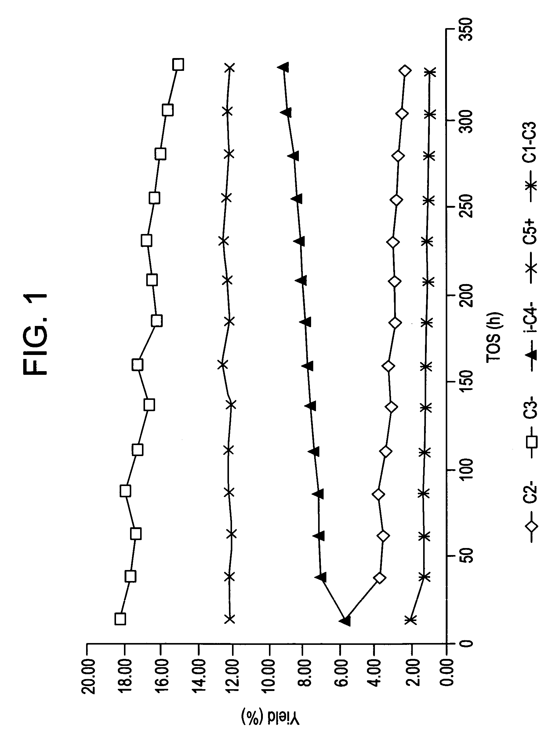
[0076]In this example, a light cracked naphtha (LCN) was cracked over a crystalline silicate. The catalyst was silicalite, formulated with a binder, which had been subjected to a pre-treatment (as described hereinbelow) by being heated (in steam), subjected to a de-alumination treatment with a complex for aluminum thereby to extract aluminum therefrom, and finally calcined. Thereafter the catalyst was employed to crack olefins in a hydrocarbon feedstock with the effluent produced by the catalytic cracking process having substantially the same olefin content as in the feedstock.

[0077]In the pre-treatment of the catalyst, a silicalite available in commerce under the trade name S115 from the company UOP Molecular Sieve Plant of P.O. Box 11486, Linde Drive, Chickasaw, Ala. 36611, USA was extruded into pellets with a binder comprising precipitated silica, the binder comprising 50 wt % of the resultant silicalite / binder combination. In greater detail, 538 g of precipitated silica (availab...

example 2

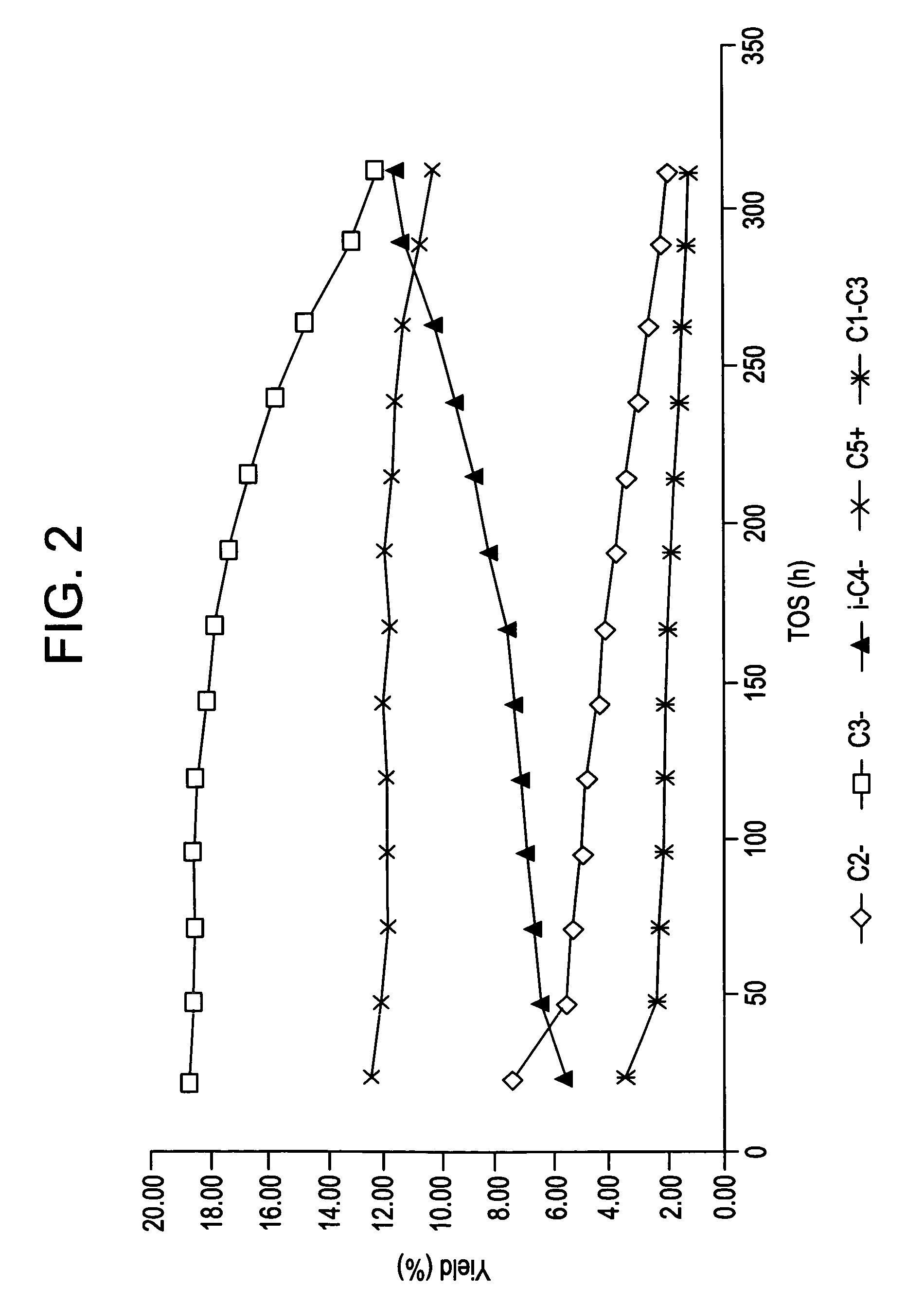
[0090]Example 1 was repeated but using a different feedstock comprising, rather than a light cracked naphtha, a fractionated C5 cut from a light cracked naphtha. In addition, in the catalytic cracking process the inlet temperature was 548° C. The hydrocarbon outlet pressure was around 1 bar (i.e. atmospheric pressure).

[0091]Table 4 shows the distribution of the hydrocarbon species in the feed of the C5 cut from the LCN, in the hydrotreated feed which had been subjected to a diene hydrogenation process as in Example 1, and in the effluent after the cracking process. It may be seen that the feed substantially initially comprises C5 species and that following the catalytic cracking process, the olefin content has remained substantially the same but the amount of C5 species in the effluent is significantly decreased as compared to the amount of such species in the initial feedstock. Again, the C2 to C4 lighter olefins may readily be fractionated from the effluent, leaving a C5+ liquid p...

example 3

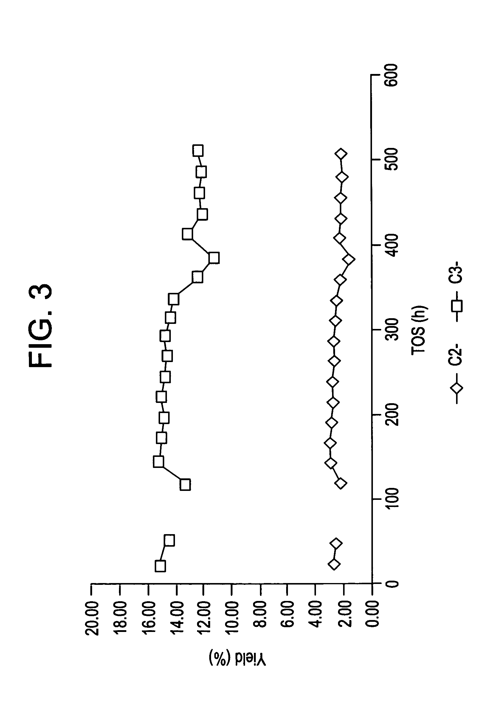
[0093]Example 1 was repeated but using as the feedstock, instead of a light cracked naphtha, a C4 raffinate (raffinate II) from an MTBE unit in a refinery. In addition, the inlet temperature of the feedstock was around 560° C. The hydrocarbon outlet pressure was around 1 bar (atmospheric pressure).

[0094]It may be seen from Tables 7 to 9 that C2 and primarily C3 olefins are produced from the C4 olefinic feedstock in accordance with the invention. In the effluent, around 34.5% of the olefin content is present as C2 and / or C3 olefins. The C2 and / or C3 olefins may be readily be fractionated from the effluent. The propylene yield on an olefin basis was 29%.


PUM

PropertyMeasurementUnit
inlet temperatureaaaaaaaaaa
temperatureaaaaaaaaaa

Abstract

A process for the production of propylene from an olefinic feedstock containing at least one olefin of C4 or greater, the process comprising contacting the olefinic feedstock with a catalyst of the MFI-type having a silicon/aluminum atomic ratio of at least about 180 to produce an effluent containing propylene, the propylene yield on an olefin basis being from 30 to 50k based on the olefinic content of the feedstock.

Description

BACKGROUND TO THE INVENTION[0001]The present invention relates to a process for the production of propylene from an olefinic feedstock.DESCRIPTION OF THE PRIOR ART[0002]It is known in the art to use zeolites to convert long chain paraffins into lighter products, for example in the catalytic dewaxing of petroleum feedstocks. While it is not the objective of dewaxing, at least parts of the paraffinic hydrocarbons are converted into olefins. It is known in such processes to use crystalline silicates for example of the MFI type, the three-letter designation “MFI” representing a particular crystalline silicate structure type as established by the Structure Commission of the International Zeolite Association. Examples of a crystalline silicate of the MFI type are the synthetic zeolite ZSM-5 and silicalite and other MFI type crystalline silicates are known in the art.[0003]GB-A-1323710 discloses a dewaxing process for the removal of straight-chain paraffins and slightly branched-chain para...

Claims


Application Information

Patent Timeline
Patent Type & Authority Patents(United States)
IPC IPC(8): B01J29/035B01J29/40C07B61/00C07C4/06C07C11/06C10G11/05
CPCC07C4/06C07C11/06C07C2529/035C07C2529/40C10G2400/20Y02P20/52C10G11/05
Inventor DATH, JEAN-PIERREDELORME, LUCGROOTJANS, JACQUES-FRAN.CEDILLA.OISVANHAEREN, XAVIERVERMEIREN, WALTER
Owner FINA RES SA
Why Eureka
Try Eureka