
Red light emitting phosphor, its production and light emitting device

a technology of light-emitting phosphor and red light-emitting phosphor, which is applied in the direction of discharge tube luminescent screen, discharge tube/lamp details, luminescent composition, etc., can solve the problem of inability to produce white light with a high luminance, imposed an upper limit on the amount of phosphor used, and weak light emission, etc. problem, to achieve the effect of high luminance and high efficiency

Inactive Publication Date: 2006-01-03
FINE RUBBER KENKYUUSHO
View PDF7 Cites 23 Cited by
  • Summary
  • Abstract
  • Description
  • Claims
  • Application Information

AI Technical Summary

Benefits of technology

"The present invention provides a red light emitting phosphor that can be efficiently excited by light of wavelengths between 350 to 420 nm and has a high luminance in response to the excitation light. This phosphor can be used as a light emitting device for red color display or in combination with green and blue light emitting phosphors for white or intermediate color display. The phosphor is prepared by mixing raw materials containing elements constituting the phosphor, firing the mixture, and washing it with an aqueous solution. When used in a light emitting device, the phosphor displays a consistent color tone in response to the wavelength of the excitation light."

Problems solved by technology

However, the above-noted red light emitting phosphors have the problem of weak light emission to long-wavelength ultraviolet radiation and short-wavelength visible light (350 to 420 nm), as compared with the blue and green light emitting phosphors.
Further, an upper limit is imposed on the amount of phosphors used.
As a result, a less quantity of white light emission is available, giving rise to problems including a failure to produce white light with a high luminance.
Then, particularly for red light emitting phosphors, there arises the problem that the quantity of light emission of a phosphor changes significantly if the peak of emission wavelength of a semiconductor light emitter varies.
The conventional red light emitting phosphors are difficult to precisely reproduce a subtle color tone.

Method used


Image

  • Red light emitting phosphor, its production and light emitting device
  • Red light emitting phosphor, its production and light emitting device
  • Red light emitting phosphor, its production and light emitting device

Examples


first embodiment

[First Embodiment of Light Emitting Device]

[0053]The first embodiment of the light emitting device according to the invention is described. The first embodiment is a light emitting device comprising a semiconductor light emitter capable of emitting light having a wavelength of 350 to 420 nm, enclosed in an encapsulant, wherein the inventive red light emitting phosphor described above is dispersed in the encapsulant.

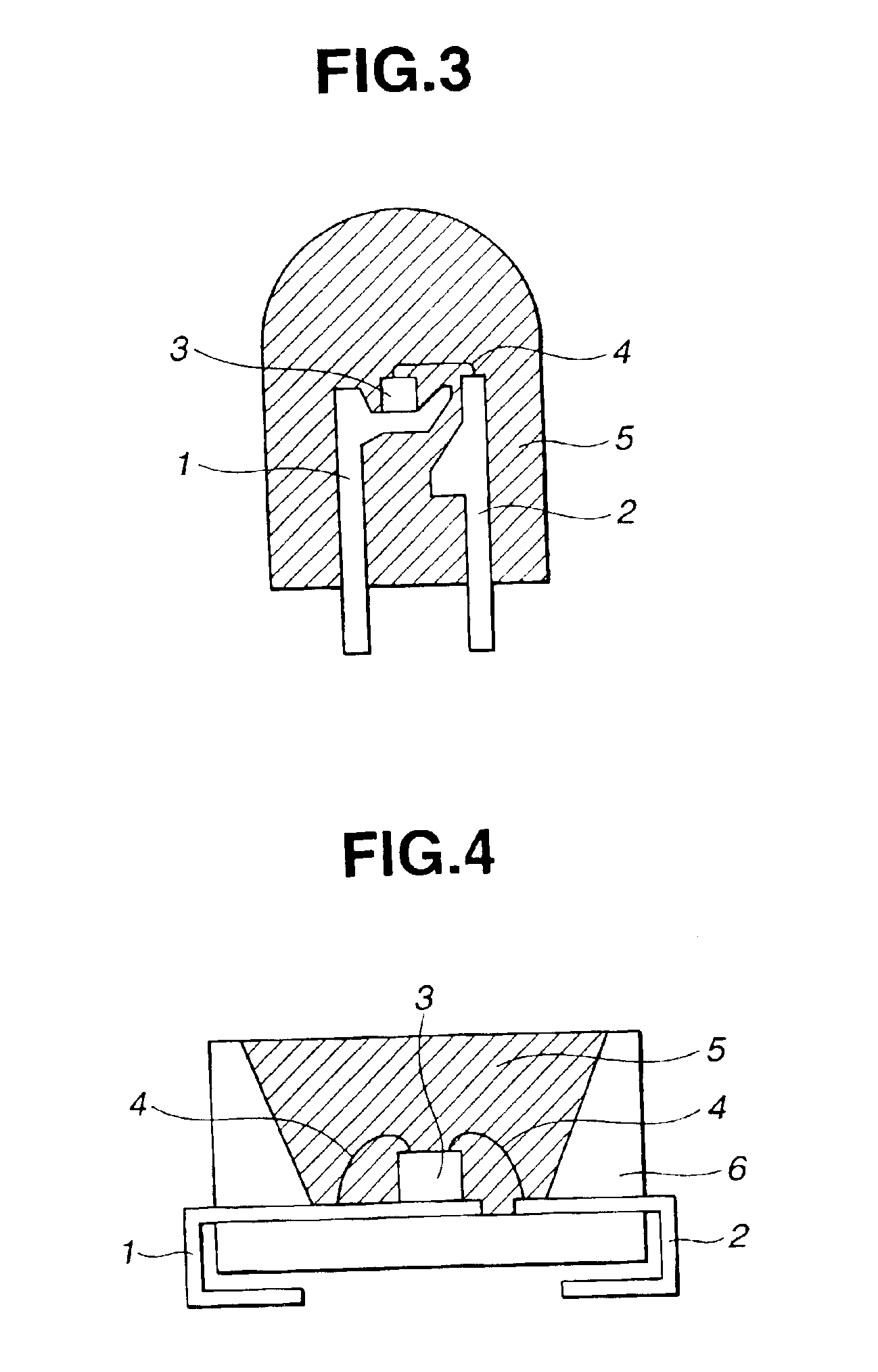
[0054]Illustrative embodiments include a so-called bullet-shaped light emitting diode of the structure wherein leads 1 and 2, a semiconductor light emitter 3 capable of emitting light having a wavelength of 350 to 420 nm, and a lead thin wire 4 electrically connecting the semiconductor light emitter 3 to the lead 2 are enclosed in an encapsulant 5 of a bullet shape, as shown in FIG. 3; and a so-called chip type light emitting diode of the structure wherein a pair of leads 1 and 2 extend from the inner bottom of an emitter casing 6 of box shape having an open top to the ou...

second embodiment

[Second Embodiment of Light Emitting Device]

[0057]The second embodiment of the light emitting device according to the invention is described. The second embodiment is a light emitting device comprising a semiconductor light emitter capable of emitting light having a wavelength of 350 to 420 nm, enclosed in an encapsulant, wherein a fluorescent layer containing the red light emitting phosphor described above is disposed in an optical path of the light from the semiconductor light emitter.

[0058]Exemplary of such devices are embodiments wherein a fluorescent layer containing the red light emitting phosphor of the invention is disposed on the semiconductor light emitter or the encapsulant. Illustrative embodiments include a so-called bullet-shaped light emitting diode of the structure wherein leads 1 and 2, a semiconductor light emitter 3 capable of emitting light having a wavelength of 350 to 420 nm, and a lead thin wire 4 electrically connecting the semiconductor light emitter 3 to th...

example 1

[0064]As phosphor-forming raw materials, 46.37 g of WO3 powder, 17.60 g of Eu2O3 powder and 3.69 g of Li2CO3 powder were weighed and uniformly mixed in a ball mill, giving a raw material mixture.

[0065]The raw material mixture was then placed in an alumina crucible where it was fired at a temperature of 900° C. for 6 hours. The fired product was thoroughly washed with pure water to remove the unnecessary soluble components, thereafter finely milled in a ball mill, and sieved (sieve opening 53 μm), yielding a red light emitting phosphor of the composition: LiEuW2O8.

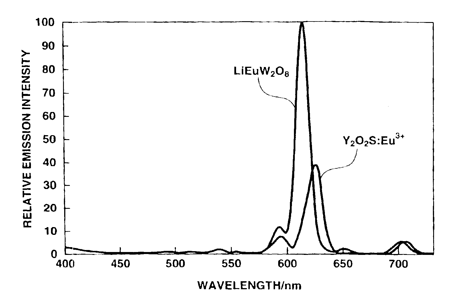
[0066]For this red light emitting phosphor LiEuW2O8, the intensity of emission upon excitation at 380 nm was determined by means of a compact spectrofluorometer FP-750 (Nihon Bunko Co., Ltd.) using a conventional Y2O2S:Eu phosphor as standard. A high value of 2.5 times the standard was recorded as shown in FIG. 10. Since the emission of LiEuW2O8 has a peak at 614 nm and the emission of Y2O2S:Eu has a peak at 624 nm, the com...


PUM

PropertyMeasurementUnit
wavelengthaaaaaaaaaa
absorption edgeaaaaaaaaaa
temperatureaaaaaaaaaa

Abstract

As a red light emitting phosphor capable of efficiently emitting red light at a high luminance in response to exciting light having a wavelength of 350-420 nm, and practically used in a light emitting device for red display or a light emitting device for white or intermediate color display in combination with green and blue light emitting phosphors, the invention provides a red light emitting phosphor capable of emitting red light upon excitation with light having a wavelength of 350-420 nm and having compositional formula (1):AEuxLn(1-x)M2O8  (1)wherein A is at least one element selected from among Li, Na, K, Rb and Cs, Ln is at least one element selected from among Y and rare earth elements exclusive of Eu, M is at least one element selected from among W and Mo, and x is a positive number satisfying 0<x≦1; and a red light emitting phosphor having compositional formula (2):D0.5EuyLn(1-y)M2O8  (2)wherein D is at least one element selected from among Mg, Ca, Sr and Ba, Ln is at least one element selected from among Y and rare earth elements exclusive of Eu, M is at least one element selected from among W and Mo, and y is a positive number satisfying 0<y≦1. Methods for preparing the red light emitting phosphors, and light emitting devices using the red light emitting phosphors are also provided.

Description

BACKGROUND OF THE INVENTION[0001]This invention relates to red light emitting phosphors capable of emitting red light upon excitation with long-wavelength ultraviolet radiation or short-wavelength visible light of 350 to 420 nm, methods for preparing the same, and light emitting devices comprising the read light emitting phosphors.[0002]Light emitting diodes (LEDs) are semiconductor light emitters adapted to produce light by converting electrical energy into ultraviolet light, visible light, infrared light or the like. For example, those emitters utilizing visible light are semiconductor light emitters formed from light emitting materials such as GaP, GaAsP and GaAlAs, and LED lamps having such emitters encapsulated with transparent resins are widely used. Also LED lamps of the display type are often used in which light emitting materials are secured to an upper surface of a printed circuit board or metal leads and encased in a transparent resin casing on which numerical figures or ...

Claims


Application Information

Patent Timeline
Patent Type & Authority Patents(United States)
IPC IPC(8): H01J1/62C09K11/68H01J63/04H01L29/201H01L29/227C01G39/00C01G41/00C09K11/77H01L33/50H05B33/04H05B33/14
CPCC01G39/006C01G41/006C09K11/7734H05B33/14C09K11/7739C09K11/7789C09K11/7794C09K11/7736C01P2002/77C01P2002/84H01L33/502H01L2224/48091H01L2224/48247H01L2224/8592H01L2924/00014
Inventor ODAKI, TSUTOMU
Owner FINE RUBBER KENKYUUSHO
Learn More