Dynamic sulfur tolerant process and system with inline acid gas-selective removal for generating hydrogen for fuel cells

Inactive Publication Date: 2006-01-10
H2FUEL
View PDF1 Cites 17 Cited by
  • Summary
  • Abstract
  • Description
  • Claims
  • Application Information

AI Technical Summary

Benefits of technology

[0010]The present invention seeks to provide an economical, efficient and compactly configured sulfur tolerant dynamic fuel process and system and process with inline acid gas-selective removal for converting sulfur bearing carbonaceous fuels into

Problems solved by technology

They are vastly different from other power generation systems.
However, the reforming catalyst (often Ni based) are poisoned by sulfur impurities in the carbonaceous fuels at temperatures less than 800° C. and therefore a hydrodesulfurization step or sulfur adsorption bed must be added to the fuel process and system prior to the reforming step.

Method used


Image

  • Dynamic sulfur tolerant process and system with inline acid gas-selective removal for generating hydrogen for fuel cells
  • Dynamic sulfur tolerant process and system with inline acid gas-selective removal for generating hydrogen for fuel cells
  • Dynamic sulfur tolerant process and system with inline acid gas-selective removal for generating hydrogen for fuel cells

Examples


example 1

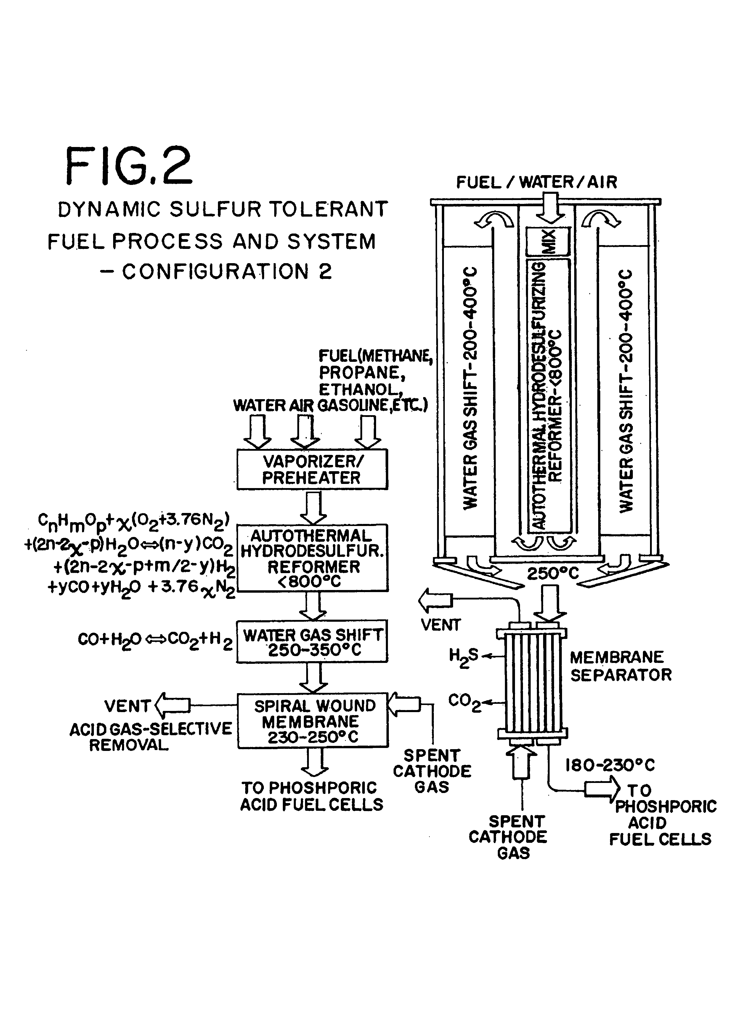
[0061]A dynamic sulfur tolerant fuel process and system having 9″ diameter and 16″ long (ASMS is not included in the dimensions) was loaded with approximate 0.5 kg of AHR catalyst (FIG. 6). The temperature in the catalyst bed was kept at about 700 to 750° C., and the pressure was kept at about 2 psig. The flow rates for the feeds were: 1.3870 gmol per minute natural gas, 3.8308 gmol per minute air, and 1.9418 gmol per minute water. Table 1 presents the AHR products, which were cooled to about 350° C. before they were directed to the single stage WGS reactor packed with our improved sulfur tolerant non-pyrophoric WGS catalyst. The gas temperature was further declined to about 250° C. across the WGS reactor. Table 2 presents the WGS products where the concentration of CO was reduced to about 0.8 mol % (dry):

[0062]The acid gas (H2S and CO2) selective removal was carried out in an ASMS. Table 3 presents the ASMS products at about 180 to 230° C. which were then fed to the PA fuel cells f...

example 2

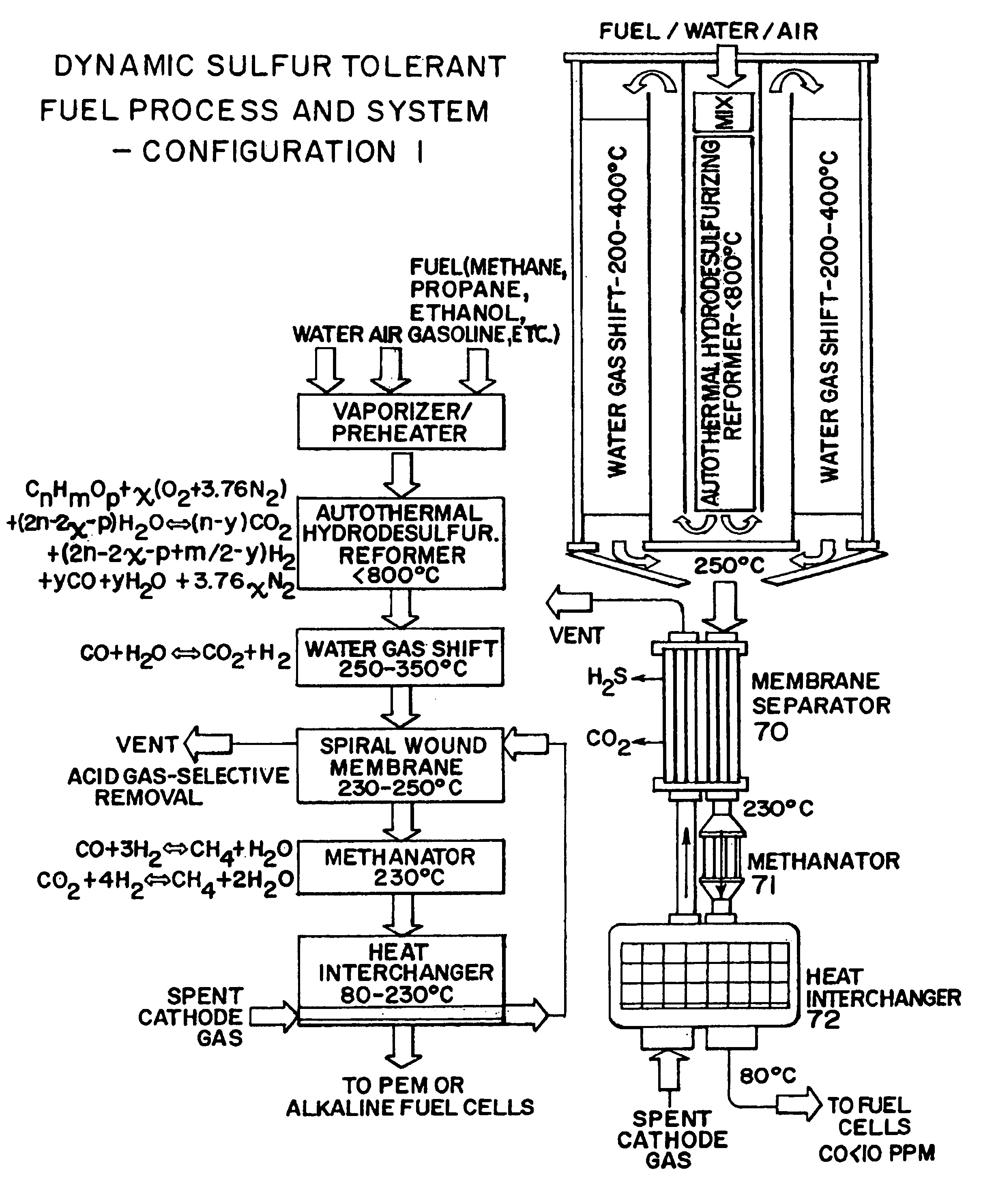
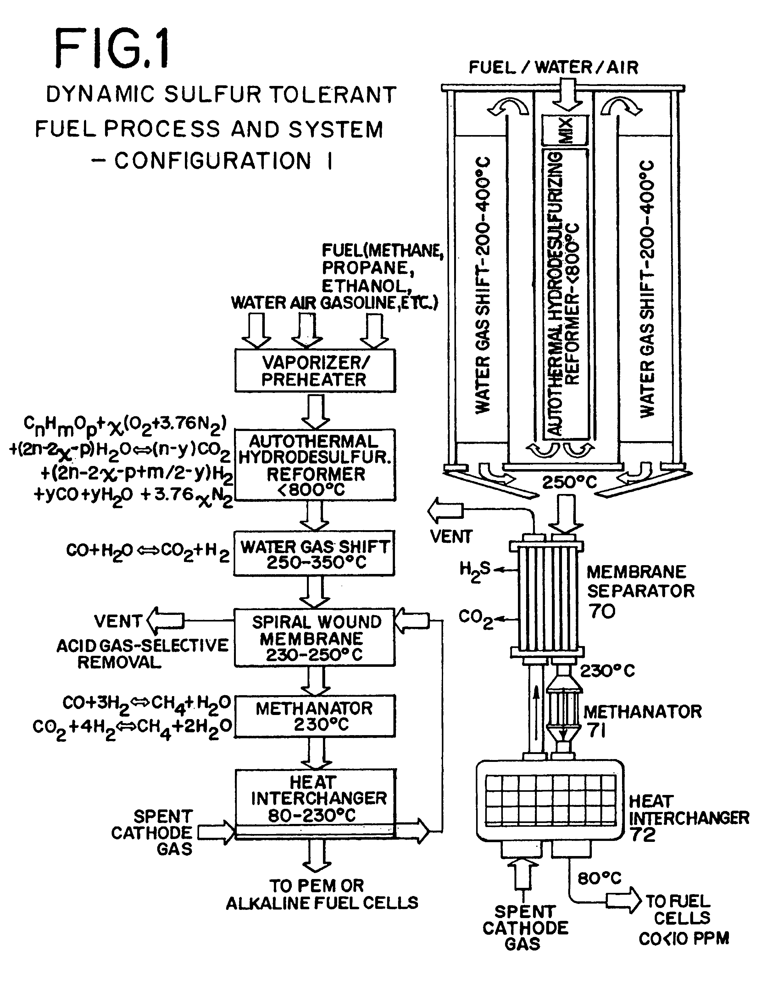
[0066]Same as Example 1 except a methanator was added after the ASMS for the final CO and CO2 contaminant reduction to appropriate levels (essentially total elimination). Table 4 presents the methanator products which were then cooled by the interchanger to about 80° C. before they were fed to the PEM or alkaline fuel cells for generating about 5.6 kWe power (FIG. 5).

[0067]

TABLE 4METHANATOR PRODUCTSASMSVol %,Vol %,LHVProductsgmol / minwetdryBtu / hrkWtkWe*H2S3.43 × 10−745 ppb52 ppbH23.498446.2853.1248,08514.085.63CO———CO2———N22.989139.5445.38CH40.09861.311.50H2O0.973112.87—TOTAL7.5592100.00100.00Efficiency**METHANATOR = 76.27% *80% fuel utilization plus 50% fuel cell stack efficiency are used in the calculations for fuel cell electric power generation **The energy efficiency (%) is defined as LHV of H2 produced / LHV of fuel input × 100

example 3

[0068]Same as Example 2 except that an AWMR was used to replace both the ASMS and methanator for the final CO contaminant reduction to less than 10 ppm levels required by the PEM fuel cells. Table 5 presents the AWMR products which were then cooled by the interchanger to about 80° C. before they were fed to the PEM fuel cells for generating about 5.8 kWe power. Since trace amounts of CO2 (256 ppm wet) still remains in the hydrogen rich gas produced by using the AWMR, a CO2 removal step is needed before it can be fed to alkaline fuel cells.

[0069]

TABLE 5AWMR PRODUCTSASMSPro-Vol %,Vol %,LHVductsgmol / minwetdryBtu / hrkWtkWe*H2S3.43 × 10−7 46 ppb 52 ppbH23.595447.7254.4749,41814.475.79CO5.6745 × 10−5 7.5 ppm 8.6 ppmCO21.9267 × 10−3256 ppm292 ppmN22.989139.6845.29CH40.01370.180.21H2O0.933512.39—TOTAL7.5336100.00100.00Efficiency**AWMR = 78.32% *80% fuel utilization plus 50% fuel cell stack efficiency are used in the calculations for fuel cell electric power generation **The energy efficiency...


PUM

PropertyMeasurementUnit
Temperatureaaaaaaaaaa

Abstract

This invention relates to a sulfur tolerant, dynamic, compact, lightweight fuel process and system that is capable of converting sulfur bearing carbonaceous fuels to hydrogen rich gases suitable for fuel cells or chemical processing applications. The process and system is based on the AHR and WGS reactions, followed by cleanup of byproduct sulfur-containing gases and carbon oxides that would otherwise poison the fuel cell electrocatalyst. Advantageously, this is accomplished via an ASMS and a methanator or an AWMR. The process and system preferably uses a special sulfur tolerant catalysts and hardware designs that enable the conversion in an energy efficient manner while maintaining desirable performance characteristics such as rapid start-stop and fast response to load change capabilities.

Description

FIELD OF THE INVENTION[0001]This invention relates to a sulfur tolerant, dynamic, compact and lightweight fuel process and system and process that is capable of converting sulfur bearing carbonaceous fuels to hydrogen rich gases suitable for fuel cells or chemical processing applications. The process is based on the autothermal hydrodesulfurizing reforming and water gas shift reactions, followed by clean up of byproduct sulfur-containing gases and carbon oxides that poison the fuel cell electrocatalyst via an acid gas-selective membrane separator and methanator or an acid gas-selective water gas shift membrane reactor. Special catalysts and hardware designs are preferably used to enable the fuel process and system to have high energy efficiency while maintaining desirable performance characteristics.BACKGROUND OF THE INVENTION[0002]A fuel cell is an electrochemical device that produces electricity from hydrogen or hydrogen rich gases without combustion, with water and heat as the on...

Claims


Application Information

Patent Timeline
IPC IPC(8): C01B3/26B01J8/04B01J19/00B01J19/24C01B3/48C01B3/50H01M8/04H01M8/06
CPCB01J8/0465B01J19/2475C01B3/48C01B3/501H01M8/0675B01J19/0013Y02E60/50B01J2208/00141B01J2208/00203B01J2208/00309B01J2208/0053C01B2203/0244C01B2203/0283C01B2203/0405C01B2203/0445C01B2203/047C01B2203/0485C01B2203/066C01B2203/0844C01B2203/1211C01B2203/127C01B2203/1282C01B2203/142C01B2203/146C01B2203/82H01M8/04022H01M8/04097H01M8/0612
Inventor RANDHAVA, SURJITHO, W. S. WINSTONKAO, RICHARD L.CAMARA, ELIAS H.
Owner H2FUEL
Why Eureka
Try Eureka