
Temperature stabilization for substrate processing

a technology of temperature stabilization and substrate, applied in the field of substrate processing, can solve the problems of insufficient use of e-beam lithography for large-volume semiconductor processing, inability to economically direct write integrated circuit patterns on wafers, and inability to meet the requirements of high-speed mechanical translation and extreme positioning precision, and achieve the effect of simplifying thermal managemen

Active Publication Date: 2009-05-05
KLA TENCOR TECH CORP
View PDF4 Cites 16 Cited by
  • Summary
  • Abstract
  • Description
  • Claims
  • Application Information

AI Technical Summary

Benefits of technology

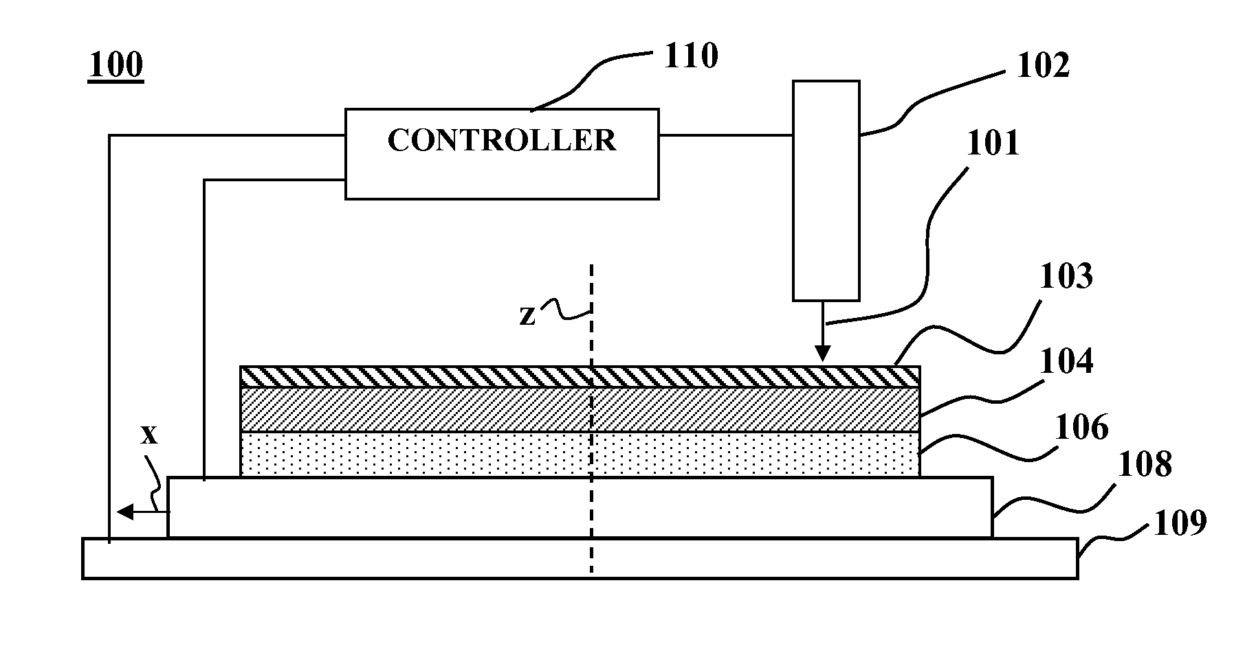
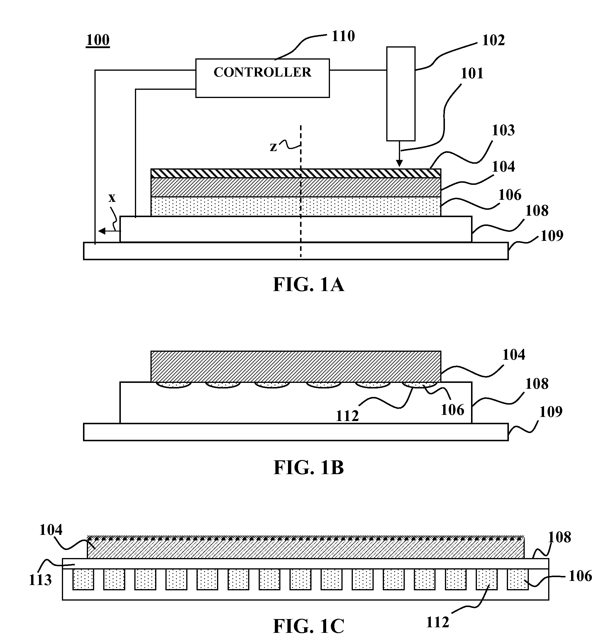
[0020]The system 100 may further include an electron beam source 102, which may be used for performing electron beam lithography on the substrate 104. The electron beam source 102 may be fixed in position and orientation relative to the susceptor 108. The electron beam source 102 directs a focused beam of electrons 101 onto a point on the surface of the substrate. The substrate may be coated with a resist 103 that, upon interaction with the electron beam 101 becomes susceptible to or resistant to removal by a solvent in subsequent development process. To facilitate patterning of the resist 103 by the electron beam 101, the susceptor 108 may include a motor and / or bearings to facilitate translational motion of the substrate 104 along an axis x that is more or less parallel top a plane of the substrate 104. The susceptor 108 may be mounted to a translating mechanism 109 that can translate the susceptor 108 along an axis y that is more or less perpendicular to the axis x and more or less parallel top a plane of the substrate 104. The electron beam source 102, susceptor 108 and translating mechanism 109 may operate under signals from a controller 110. The controller 110 may direct the electron beam source 102 to selectively adjust an electron beam current (e.g., by turning the electron beam 101 on and off) as the susceptor 108 translates so that electron beam direct write lithography may be performed along a predetermined path on the substrate 104.
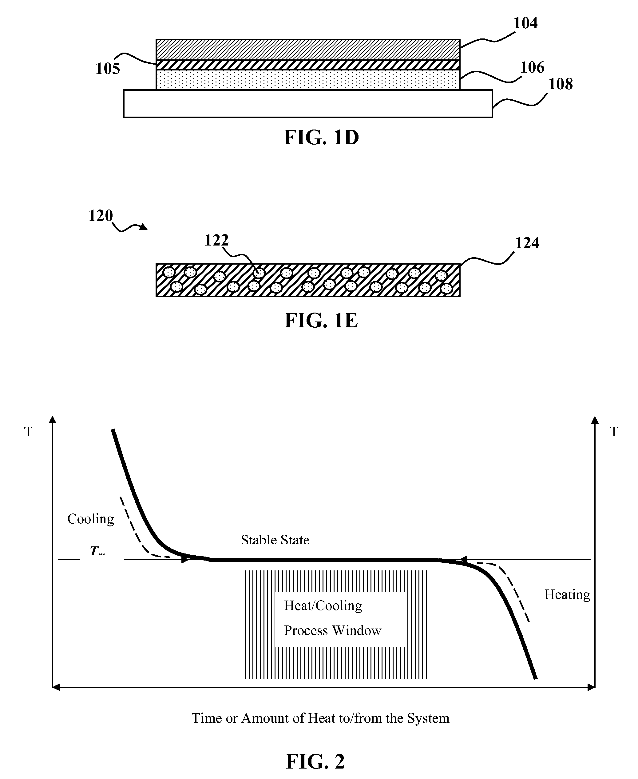
[0025]This concept allows two thermal management tasks to be accomplished simultaneously. First, the system may be cooled down (or heated up) only by internal means, i.e. utilizing the phase transition to balance thermal energy flow into or out of the substrate 104. In addition, the temperature of the substrate 104 may be stabilized without having to use additional supporting electrical, mechanical or other types of temperature stabilization devices during processing of the substrate 104. Specifically, phase-transition drive temperature regulation may be implemented without having to provide any external heat transfer channel, e.g., by conduction, convection or radiation. Specifically, phase-transition driven temperature stabilization may be implemented during processing without having to employ complicated cooling channels for heat transfer by gas or liquid convection, backside gas for conduction, or thermoelectric effect. Such heat transfer mechanisms may be particularly difficult and expensive to implement, e.g., where the susceptor 108 is moving at high speed. The heat transfer material 106 and / or susceptor 108 and / or substrate 104 may be cooled down or warmed up to a desired temperature for processing, e.g., the melting temperature Tm, before processing the substrate 104. Such pre-process cooling or heating may be implemented by placing the substrate 104 and / or heat transfer material 106 and / or susceptor 108 in thermal contact with heat sink having the desired temperature and allowing them to come to thermal equilibrium.
[0029]Alternatively, a heat absorbing material 106 may be embedded in a suitable compliant material. For example FIG. 1E depicts an example of a composite heat absorbing layer 120 having a nano-composite of nano-particles 122 of heat absorbing material embedded in a suitable polymer material 124. By way of example, the nano-particles 122 may be nano-particles of gallium and the suitable polymer may be a fluoropolymer elastomer such as Viton®. Such a composite heat absorbing material may provide sufficient compliance for thermal conductivity between substrate and embedded heat transfer material. The Gallium / polymer ratio and durometer of the Gallium and polymer composite may be adjusted and optimized to provide both sufficient heat capacitance and shape compliance performance.
[0030]Embodiments of the invention allow for greatly simplified thermal management during substrate processing. Such simplified thermal management may make possible the widespread use of electron beam lithography for direct writing of integrated circuit features along an arbitrary path on semiconductor wafers and other forms of high volume substrate processing.

Problems solved by technology

Due to limitations on the steppers used to translate the wafer, e-beam lithography processes in their existing configurations are too slow for economical direct writing of integrated circuit patterns on a wafer.
Consequently, e-beam lithography has not been used for large volume semiconductor processing.
The requirement of fast mechanical translation combined with extremely tough positioning precision requirements (e.g., 5 nm or better for the advanced states of technology) does not allow for significant physical contacts between the moving wafer stage and external objects.
This imposes significant limitations in providing thermal flow management and wafer temperature stabilization.
This non-uniform variation in wafer temperature distorts the wafer, introducing errors in the position of the electron beam relative to the actual wafer coordinates.
For small design rules (e.g., 65 nanometers or less), such thermally induced errors can critically affect the applicability of the e-beam direct write technique.
However, conventional approaches to thermal management (e.g., backside gas conduction, liquid or gas convection, liquid evaporation, etc.) are not compatible with the direct e-beam writing process conditions, e.g. high vacuum, fast, vibration-less motion, no physical contacts with the external objects for heat transfer to or from the wafer during processing.
However, the design of the temperature adjusting mechanism in this prior art is complicated, and particularly unsuitable for a fast moving system due to vibrations generated by the electrical wiring.
However, this cooling mechanism requires a complicated exhausted unit, which is not suitable for performing e-beam lithography under ultra-high vacuum conditions and on a rapidly moving wafer.

Method used


Image

  • Temperature stabilization for substrate processing
  • Temperature stabilization for substrate processing
  • Temperature stabilization for substrate processing

Examples


Embodiment Construction

[0017]Although the following detailed description contains many specific details for the purposes of illustration, anyone of ordinary skill in the art will appreciate that many variations and alterations to the following details are within the scope of the invention. Accordingly, embodiments of the invention as described below are set forth without any loss of generality to, and without imposing limitations upon, the claimed invention.

[0018]FIG. 1A is a cross sectional view of a temperature stabilization system according to a preferred embodiment of the present invention. As shown in FIG. 1A, system 100 includes a susceptor 108 and a heat absorbing material 106 disposed between the susceptor 108 and one or more substrates 104. The heat absorbing material 106 includes a component that undergoes solid-liquid (melting) or solid-solid (structural) phase transformation at a desired operating temperature for material processing of the substrate 104. Preferably, the heat absorbing material...


PUM

PropertyMeasurementUnit
temperatureaaaaaaaaaa
melting pointaaaaaaaaaa

Abstract

A temperature stabilization system, method, composition of matter and substrate processing system are disclosed. A heat absorbing material is disposed in thermal contact with a substrate. The heat absorbing material is characterized by a solid-liquid phase transition temperature that is in a desired temperature range for material processing the substrate. When the substrate is subjected to material processing that results in heat transfer into or out of the substrate the solid-liquid phase transition of the heat absorbing material stabilizes the temperature of the substrate.

Description

CROSS-REFERENCE TO A RELATED APPLICATION[0001]This application claims priority from provisional patent application Ser. No. 60 / 820,324, which was filed on Jul. 25, 2006, the entire disclosures of which are incorporated herein by reference.FIELD OF THE INVENTION[0002]Embodiments of the direction are directed to substrate processing. More particularly, embodiments of the invention are directed to temperature stabilization based on heat flow auto-management utilizing a solid-liquid (or solid-solid) phase transition of a material.BACKGROUND OF THE INVENTION[0003]In various fabrication processes used in semiconductor industry, a substrate such as a semiconductor wafer may be exposed to various types of the energetic treatments (plasma, energetic particles, light irradiation etc.). An example of such a process is known as electron beam (e-beam) lithography. Electron beam lithography has been used, e.g., for writing patterns, such as electrical circuit patterns, on substrates used as masks...

Claims


Application Information

Patent Timeline
Patent Type & Authority Patents(United States)
IPC IPC(8): H05B3/68F26B19/00
CPCH01L21/67103H01L21/67109G03F7/70716G03F7/70875
Inventor GOTKIS, YEHIELDONDE, ARIKLORDI, VINCENZO
Owner KLA TENCOR TECH CORP
Learn More