Diamond composite heat spreader having thermal conductivity gradients and associated methods

a technology of thermal conductivity gradient and composite heat spreader, which is applied in the direction of cooling/ventilation/heating modification, semiconductor device details, semiconductor/solid-state device details, etc., can solve the problems of insufficient cooling of future generations of cpus, insufficient heat dissipation methods, etc., to achieve improved heat transfer control, variable thermal conductivity, and high thermal conductivity

Inactive Publication Date: 2006-01-17
RITEDIA CORPORATION
View PDF40 Cites 78 Cited by
  • Summary
  • Abstract
  • Description
  • Claims
  • Application Information

AI Technical Summary

Benefits of technology

[0017]Accordingly, the present invention provides composite heat spreaders that can be used to draw or conduct heat away from a heat source. In one aspect, a diamond composite heat spreader can have a variable thermal conductivity gradient which improves control of heat transfer through the heat spreader. A diamond-containing region of the heat spreader can contain diamond particles such that the diamond concentration and / or the diamond particle size are varied to produce a desired thermal conductivity gradient throughout the heat spreader. Regions proximate to a heat source can have a higher thermal conductivity than regions further away from the heat source.
[0018]By providing a variable thermal conductivity gradient, more expensive materials such as diamond film and larger diamond particles can be selectively used in regions closer to a heat source, while allowing for cheaper smaller diamond particles and materials to be used farther away from the heat source where available volumes are larger so thermal conductivity can be lower without sacrificing overall performance.

Problems solved by technology

Along with such advances comes various design challenges.
One of the often overlooked challenges is that of heat dissipation.
Most often, this phase of design is neglected or added as a last minute design before the components are produced.
Current methods of heat dissipation, such as by using metal (e.g., Al or Cu) fin radiators, and water evaporation heat pipes, will be inadequate to sufficiently cool future generations of CPUs.
However, such materials have a thermal conductivity that is no greater than that of Cu, hence, their ability to dissipate heat from semiconductor chips is limited.
When the chip is heated to above 60° C., the mismatch of thermal expansions between metal and ceramics can create microcracks.
The repeated cycling of temperature tends to aggravate the damage to the chip.
As a result, the performance of the semiconductor will deteriorate.
Moreover, when temperatures reach more than 90° C., the semiconductor portion of the chip may become a conductor so the function of the chip is lost.
In addition, the circuitry may be damaged and the semiconductor is no longer usable (i.e. becomes “burned out”).
Although heat pipes and heat plates may remove heat very efficiently, the complex vacuum chambers and sophisticated capillary systems prevent designs small enough to dissipate heat directly from a semiconductor component.
As a result, these methods are generally limited to transferring heat from a larger heat source, e.g., a heat sink.
However, large area diamonds are very expensive; hence, diamond has not been commercially used to spread the heat generated by CPUs.
This high price would prohibit diamond heat spreaders from being widely used except in those applications (e.g., high power laser diodes) where only a small area is required or no effective alternative heat spreaders are available.
In addition to being expensive, CVD diamond films can only be grown at very slow rates (e.g., a few micrometers per hour); hence, these films seldom exceed a thickness of 1 mm (typically 0.3-0.5 mm).
As a result, most PCD compacts have a relatively small diamond table thickness, e.g., about 0.5 mm, that limits their use as a heat spreader for large components.
Such PCD compacts are of limited use in the field of heat spreaders because of their limited physical capacity to transfer or conduct heat.

Method used


Image

  • Diamond composite heat spreader having thermal conductivity gradients and associated methods
  • Diamond composite heat spreader having thermal conductivity gradients and associated methods
  • Diamond composite heat spreader having thermal conductivity gradients and associated methods

Examples


example 1

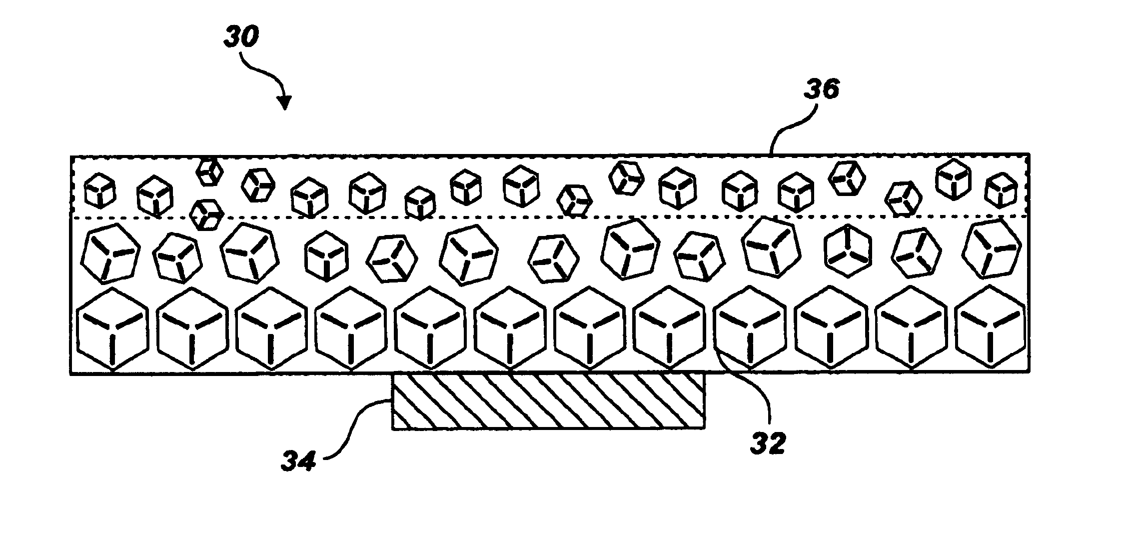
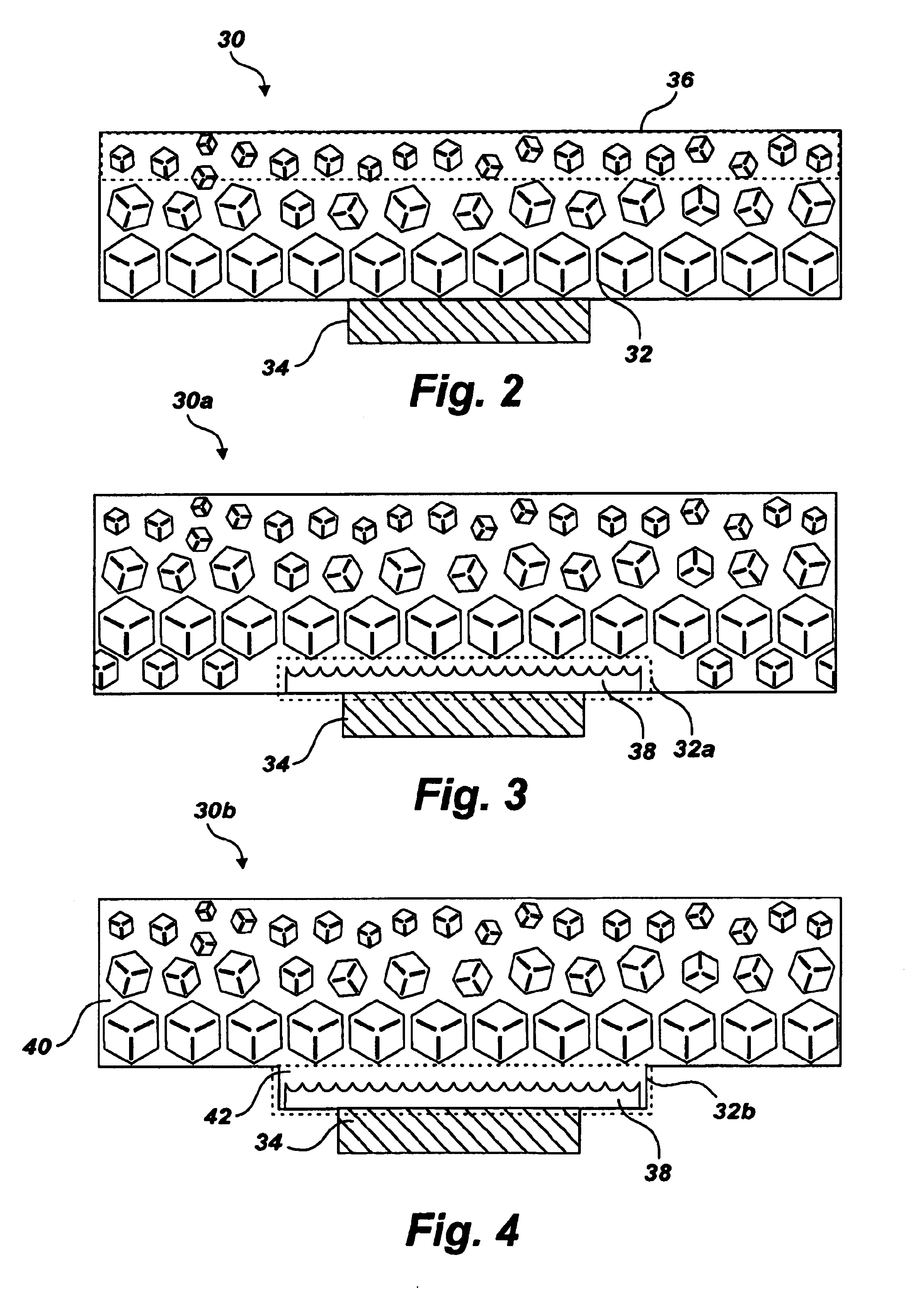
[0124]Diamond particles of 50 / 60 U.S. mesh are mixed with powdered copper to form a mixture. This mixture is then cold pressed to form a slug. A thin walled mold made of a refractory metal (e.g., Ti, Zr, W, Mo, Ta) is provided. Ceramic particles (e.g., SiC, Si3N4, Al2O3) having a coarse grain size (e.g., 40 / 50 mesh) are first put in the mold and then the ceramic particles are covered with the diamond-copper slug. The sample assembly is then placed in a high-pressure cell and pressurize to over 5 GPa. The assembly is then heat charged to over 1200° C. by passing an electric current through a heating tube that surrounds the sample assembly. At this temperature and pressure, copper melts and is forced out from between the diamond particles. The liquid copper flows to the bottom of the mold containing the ceramic particles. The ceramic particles contain ample empty pores to receive the liquid copper. In this way the diamond grains are partially crushed and substantially fill in the spac...

example 2

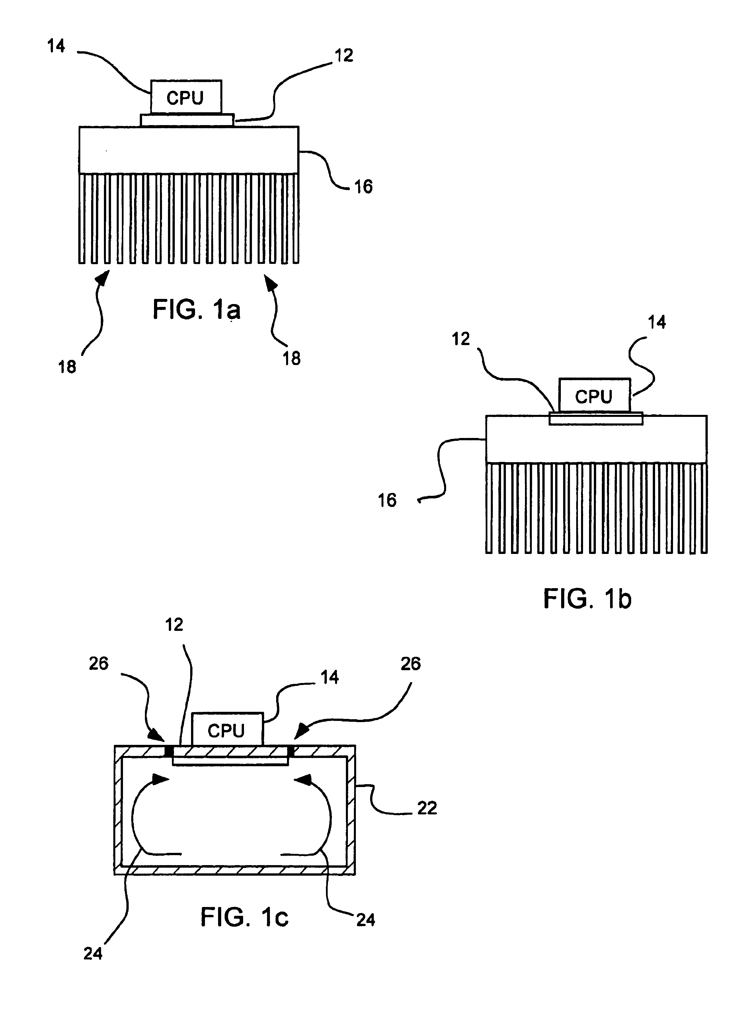
[0128]A contact cavity in the form of a circular hole having a diameter of about 20 mm is formed into a flat base of an aluminum heat sink with radiating fins cooled by a fan. The contact cavity is coated with a thermal grease and includes a pin hole near the center of the cavity. The heat sink is heated to a temperature of about 200° C. to expand the contact cavity, after which a diamond composite heat spreader with a diameter of about 20 mm is inserted into the contact cavity. The pin hole ensures that no air is trapped between the heat spreader and heat sink and allows for excess thermal grease to be extruded therethrough. Upon cooling, the much larger thermal expansion contraction of the aluminum heat sink will result in the diamond composite heat spreader being firmly compressed into the contact cavity. The top surface of the diamond composite heat spreader is ground to remove any debris formed by the shrink fitting. The heat spreader is placed in contact with a chip or CPU and...

example 3

[0129]50 / 60 U.S. mesh diamond particles were acid cleaned and loaded in a tatalum cup having a cylindrical shape. An OFHC copper disk was placed on top of the diamond particles. The charge was pressurized to 5.5 GPa in a 2000 ton cubic press that utilizes 6 anvils pressing toward a pyrophllite cube that contained the charge. Electrical current was passed through a graphite tube that surrounds the charge. At a temperature of 1150° C., molten copper was infiltrated through the diamond particles. Upon cooling and decompression, the charge was ground to remove the tantalum container and also the top and bottom surfaces of the diamond-copper composite. The final disk was 50.8 mm in diameter and 3 mm thick. The diamond content was approximately 90 vol %. Over 200 diamond composite heat spreaders were produced, resulting diamond-copper heat spreaders having a heat transfer rate of about 1.5-2.5 times that of pure copper.


PUM

PropertyMeasurementUnit
thicknessaaaaaaaaaa
thicknessaaaaaaaaaa
poweraaaaaaaaaa

Abstract

A diamond composite heat spreader having a variable thermal conductivity gradient can improve control of heat transfer based on a specific application. A diamond-containing region of the heat spreader can contain diamond particles such that the diamond concentration and / or the diamond particle size a varied to produce a desired thermal conductivity gradient. Regions proximate to a heat source can have a higher thermal conductivity than regions further away from the heat source. Thin diamond films can also be used in conjunction with the particulate diamond in order to provide a region of maximum thermal conductivity adjacent a heat source. By providing a variable thermal conductivity gradient, more expensive materials such as diamond film and larger diamond particles can be selectively used in regions closer to a heat source, while allowing for cheaper smaller diamond particles and materials to be used farther away from the heat source where thermal conductivity can be lower without sacrificing overall performance.

Description

PRIORITY INFORMATION[0001]This application is a continuation-in-part of U.S. patent application Ser. No. 10 / 453,469, filed Jun. 2, 2003 and of U.S. patent application Ser. No. 10 / 270,018, filed Oct. 11, 2002, which are each incorporated by reference herein.FIELD OF THE INVENTION[0002]The present invention relates to carbonaceous composite devices and systems that can be used to conduct or absorb heat away from a heat source. Accordingly, the present invention involves the fields of chemistry, physics, semiconductor technology, and materials science.BACKGROUND OF THE INVENTION[0003]Progress in the semiconductor industry has been following the trend of Moore's Law that was proposed in 1965 by then Intel's cofounder Gordon Moore. This trend requires that the capability of integrated circuits (IC) or, in general, semiconductor chips double every 18 months. Thus, the number of transistors on a central processing unit (CPU) in 2002 may approach 100 million. As a result of this densificati...

Claims


Application Information

Patent Timeline
Patent Type & Authority Patents(United States)
IPC IPC(8): H01L23/373
CPCH01L23/373H01L23/3732H01L23/3733H01L2924/01322H01L2924/0002H01L2924/00H05K7/20
Inventor SUNG, CHIEN-MIN
Owner RITEDIA CORPORATION
Why Eureka
Try Eureka