

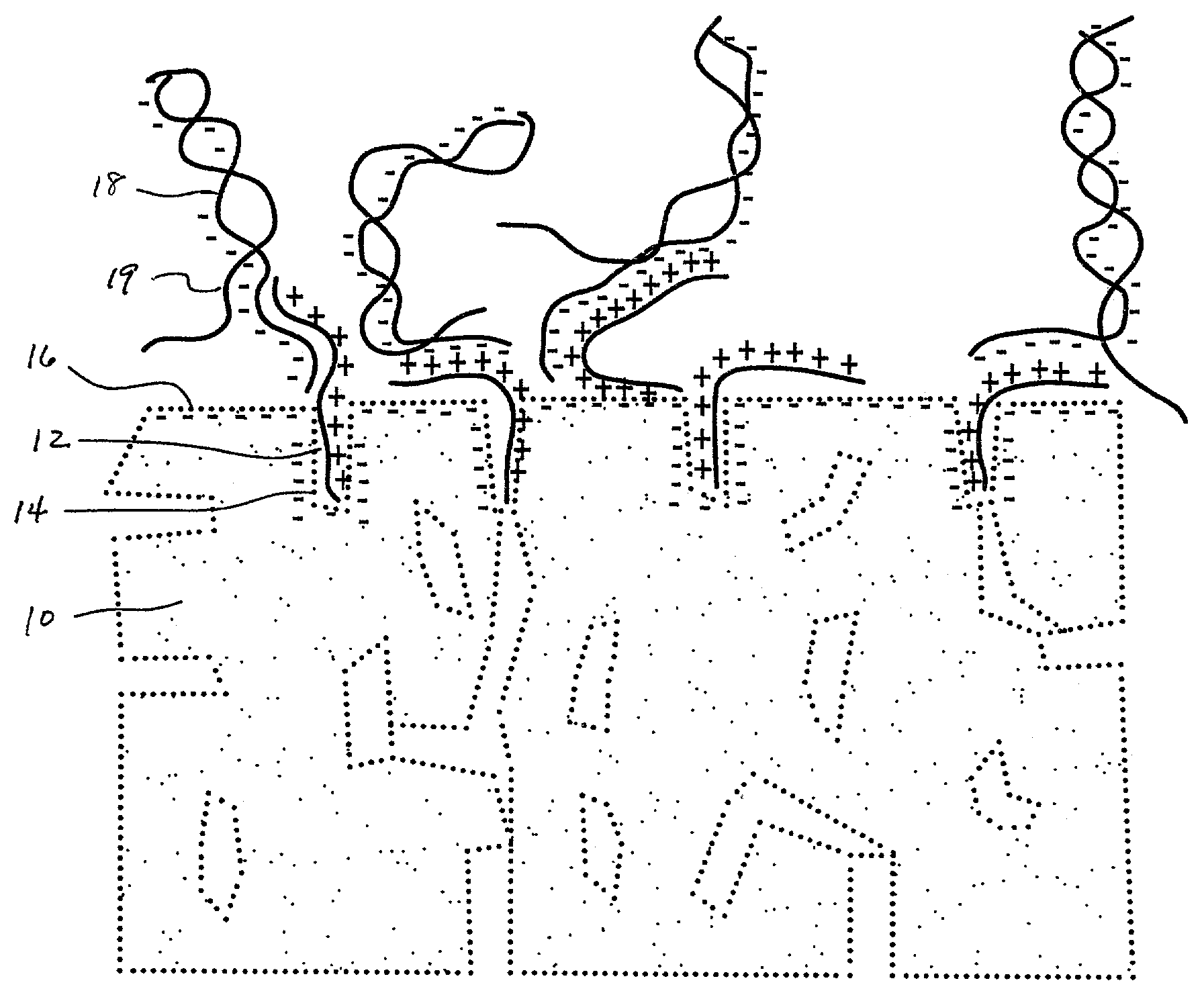
Porous substrates for DNA arrays
a technology of porous substrates and dna arrays, applied in the direction of sugar derivatives, alkali metal oxides/hydroxides, immobilised enzymes, etc., can solve the problems of low fluorescent signal-to-noise ratio, uncertain or erroneous, cross-talk and contamination, etc., to increase the overall positive charge
- Summary
- Abstract
- Description
- Claims
- Application Information
AI Technical Summary
Benefits of technology
Problems solved by technology
Method used
Image

Examples
example
[0022]A number of 1×3 inch×1 mm porous glass slides (Vycor®, Corning Code 7930) were coated with gama-amino-propyltriethoxylsilane (GAPS) using a 1.0% aqueous solution of GAPS at a pH of 4.0, adjusted using acetic acid. Generally, the treatment can be applied at any acidic pH value. Applicable pH values will range typically between about 5 or 6 to about 2 or 1, more preferably about 3 or 4. The coatings were done by completely immersing each slide in the silane solution (dip-coating) for about 30 minutes. The coated slides were then washed thoroughly with distilled water and dried. The slides were then heated to 160° C. in order to cross-link any free silanol groups. Temperatures can range from about 140–175° C., but more typically between 150–170° C.
[0023]Next, a water and glycerin solution containing Cy3-labeled single stranded 80-mer oligonucleotides in a concentration of 1 picomole oligo per microliter was printed using a micropipette onto the treated slide surface. The printed ...
PUM
| Property | Measurement | Unit |
|---|---|---|
| temperature | aaaaa | aaaaa |
| area | aaaaa | aaaaa |
| surface area | aaaaa | aaaaa |
Abstract
Description
Claims
Application Information