Eureka AIR delivers breakthrough ideas for toughest innovation challenges, trusted by R&D personnel around the world.

Cemented carbide tool and method of making

a cutting tool and cemented carbide technology, applied in the field of cemented carbide cutting tools, can solve the problems of increasing the cost of storing (and/or making) two or more different compositions of starting powder, and achieve the effect of high nitrogen content and high nitrogen conten

Inactive Publication Date: 2006-02-14
KENNAMETAL INC
View PDF82 Cites 42 Cited by
  • Summary
  • Abstract
  • Description
  • Claims
  • Application Information

AI Technical Summary

Benefits of technology

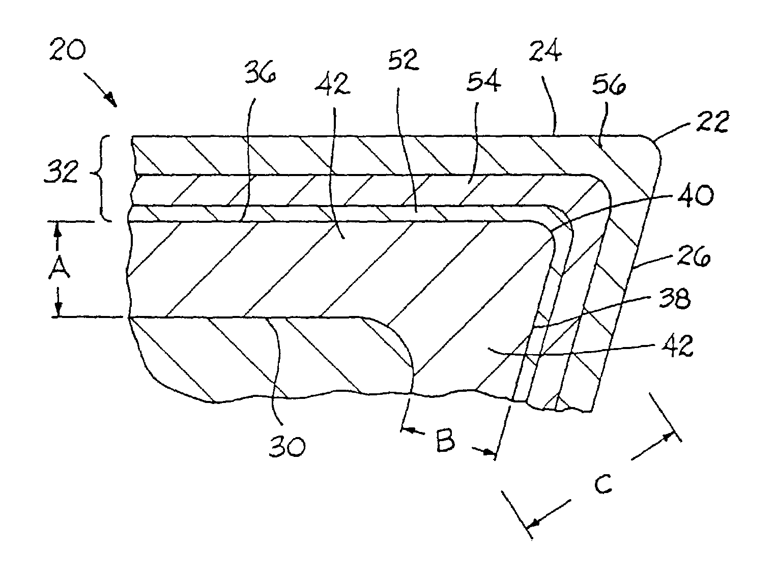
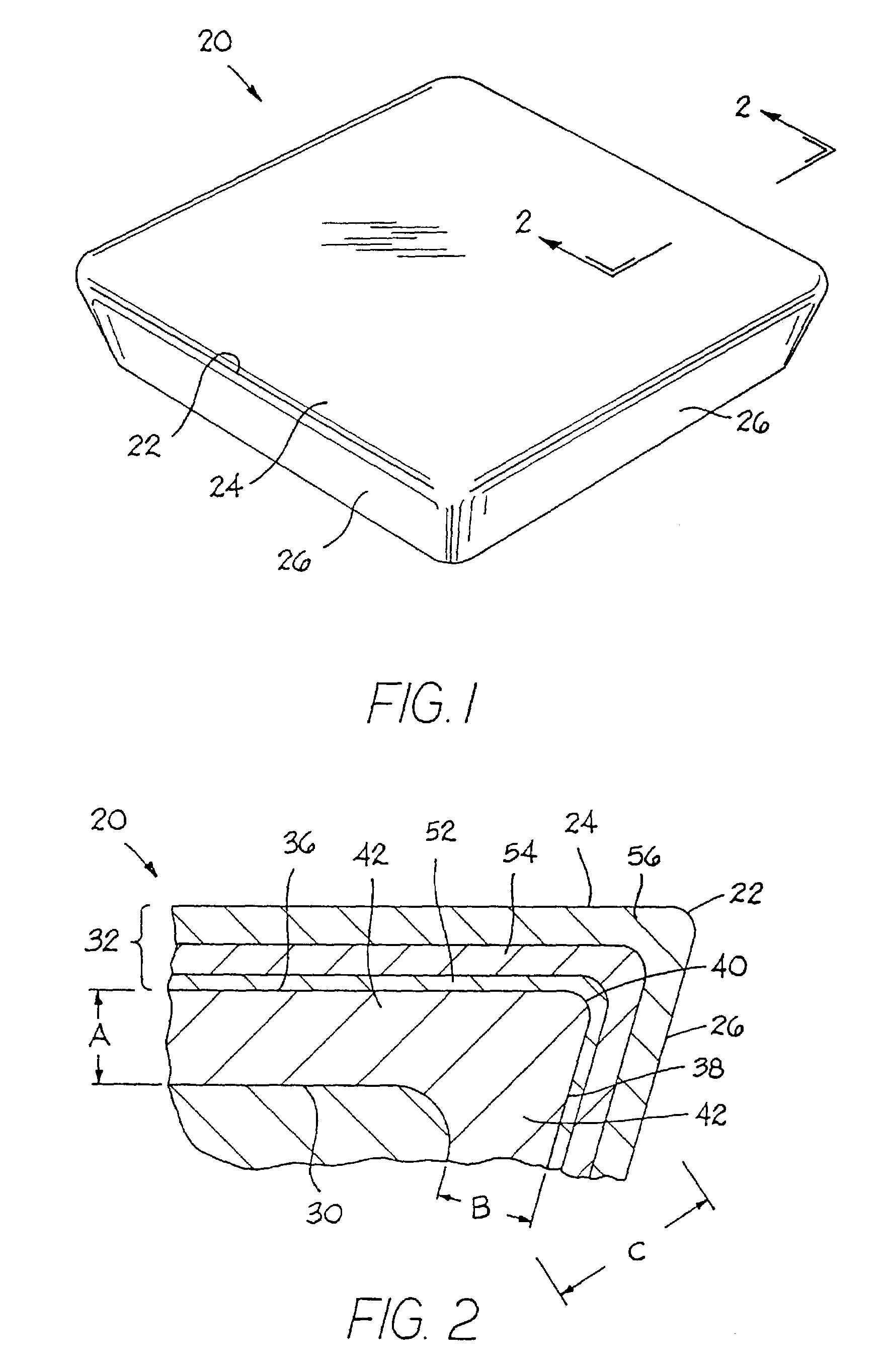
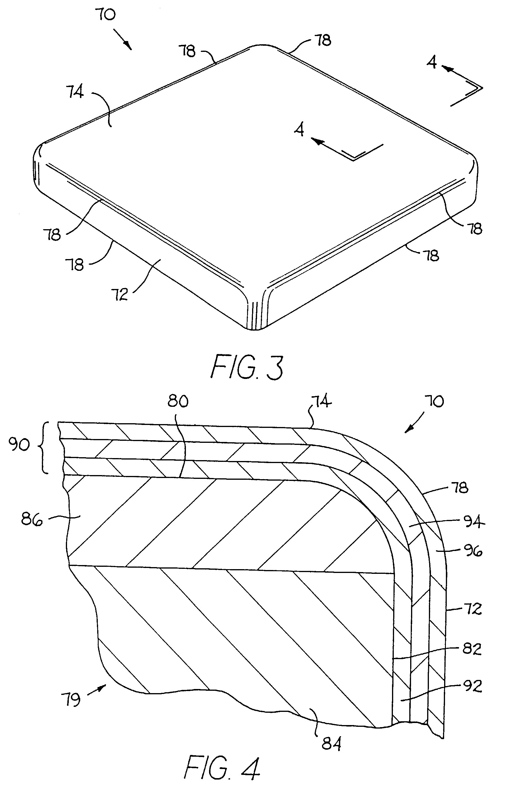
[0020]In still another form thereof, the invention is a coated cutting insert that comprises a substantially fully dense substrate made by sintering a compacted mass of starting powders in an atmosphere containing a nitrogen partial pressure. The starting powders include the following components: a binder selected from one or more of cobalt, nickel, iron and their alloys wherein the binder is present between about 3 weight percent and about 12 weight percent, up to about 95 weight percent tungsten, up to about 7 weight percent carbon, and up to about 13 weight percent of one or more of the following components: titanium, tantalum, niobium, hafnium, zirconium, and vanadium. The substrate has a rake surface and a flank surface, and there is a cutting edge being at the intersection of the rake and flank surfaces. The substrate has a zone of non-stratified binder enrichment of a generally uniform depth beginning adjacent to and extending inwardly from the cutting edge and at least one of the rake surface and the flank surface toward a bulk region. The zone of binder enrichment has a high nitrogen content, and the bulk region of the substrate has a high nitrogen content. There is a coating on the cutting edge and at least a portion of one or both of the rake surface and the flank surface of the substrate.
[0021]In another form thereof, the invention is a method of making a coated cemented carbide cutting insert comprising the steps of: blending starting powders to form a starting powder mixture wherein the powders contain the following components: a binder selected from one or more of cobalt, nickel, iron and their alloys, tungsten, carbon, and one or more of the following: titanium, tantalum, niobium, hafnium, zirconium, and vanadium; pressing the starting powder mixture to form a green cutting insert blank; dewaxing the green cutting insert blank to form a dewaxed cutting insert blank; sinter heating the dewaxed cutting insert blank from about the maximum dewaxing temperature to at least a pore closure temperature in an atmosphere having a first nitrogen partial pressure for substantially the entire sinter heating step so as to form a pre-sintered cutting insert blank; sinter holding the pre-sintered cutting insert blank at a sinter hold temperature in an atmosphere having a second nitrogen partial pressure for substantially the entire sinter holding step to form a sintered cutting insert blank wherein the second nitrogen partial pressure is greater than the first nitrogen partial pressure; cooling the sintered cutting insert blank from the sintering temperature to a target temperature below the eutectic temperature so as to form an as-sintered cutting insert substrate having a peripheral surface with a zone of non-stratified binder enrichment beginning adjacent to and extending inwardly toward a bulk region of the substrate; and coating the as-sintered cutting insert substrate with a coating comprising one or more layers including a base layer on the surface of the substrate, and the base layer comprising a material containing nitrogen.
[0022]In still yet another form thereof, the invention is a method of selectively making either as as-sintered substrate that exhibits a surface zone of binder enrichment or an as-sintered substrate that does not exhibit a surface zone of binder enrichment, the method comprising the steps of: blending starting powders with an effective amount of nitrogen being absent and containing a binder alloy selected from one or more of cobalt, nickel, iron and their alloys, tungsten, carbon, and one or more of the following: titanium, tantalum, niobium, hafnium, zirconium, and vanadium; pressing the starting powder mixture to form a green cutting insert blank; dewaxing the green cutting insert blank to form a dewaxed cutting insert blank; sinter heating the dewaxed cutting insert blank from the maximum dewaxing temperature to at least a pore closure temperature in an atmosphere having a first nitrogen partial pressure for substantially all of the entire sinter heating step so as to form a pre-sintered cutting insert blank; sinter holding the pre-sintered cutting insert blank at a sinter hold temperature in an atmosphere having a second nitrogen partial pressure for substantially the entire sinter holding step as to form a sintered cutting insert blank and wherein the second nitrogen partial pressure may selectively be either greater than equal to or less than the first nitrogen partial pressure; cooling the sintered cutting insert blank from the sintering temperature to a target temperature below the eutectic temperature so as to form an as-sintered cutting insert substrate wherein when the second nitrogen partial pressure is greater then the first nitrogen partial pressure the as-sintered cutting insert substrate does not exhibit a surface zone of binder enrichment and when second nitrogen partial pressure is equal to or less than the first nitrogen partial pressure the as-sintered cutting insert substrate exhibits a surface zone of binder enrichment; and coating the as-sintered cutting insert substrate with a coating comprising one or more layers.

Problems solved by technology

As can be appreciated, there is an increase in the cost associated with storing (and / or making) two or more different compositions of starting powder as compared with the cost of storing (and / or making) only one composition of starting powder.

Method used


Image

  • Cemented carbide tool and method of making
  • Cemented carbide tool and method of making
  • Cemented carbide tool and method of making

Examples


example no.1

EXAMPLE NO. 1

[0083]For Example No. 1, the starting powder mixture contained the following components: 6 weight percent cobalt, 2.7 weight percent tantalum, 2.0 weight percent titanium, 0.8 weight percent niobium and the balance of the starting powder mixture was tungsten and carbon wherein the carbon was adjusted to a level of 6.18 weight percent. The starting powder mixture did not contain any nitrogen, except possibly in small trace amounts. These trace amounts were sufficiently small so that the starting powder did not contain any effective amount of nitrogen wherein the nitrogen (even if present) in the starting powder did not assist in any measurable (or perceivable) way in the formation of the zone of binder enrichment.

[0084]Five kilograms (kg) of the powder mixture charge for Inventive Example No. 1 were added to a 7.5 inch inside diameter by 9 inch steel mill jar along with 21 kilograms of 5 / 16 th inch diameter cemented carbide cycloids. Heptane was added to the top of the j...

example no

[0093]A powder mixture of the same composition as Example No. 1 was prepared, pressed and processed in the same way as Example No. 1, except that during the controlled cooling step the nitrogen partial pressure was at 70 torr. An analysis showed that there was a zone of essentially non-stratified binder enrichment beginning at the peripheral surface of the substrate and extending inwardly to a depth of about twenty-nine micrometers. The apparent porosity of the zone of binder enrichment was C00 and of the bulk substrate was C02.

example no.2

EXAMPLE NO. 2

[0094]For Example No. 2, green cutting insert blanks were pressed from the same powder mixture as Example No. 1 into SNG432 style green cutting insert blanks. The processing steps were the same as those used to process Example No. 1, except that the sinter hold step had a duration of about forty-five minutes. The depth of the zone of essentially non-stratified binder enrichment was about twenty-three micrometers and the maximum level of cobalt concentration in the zone of binder enrichment was between about 200 percent and about 250 percent of the cobalt concentration of the bulk substrate. The porosity rating for the zone of binder enrichment was C00 and the bulk substrate was C02.


PUM

PropertyMeasurementUnit
weight percentaaaaaaaaaa
depthaaaaaaaaaa

Abstract

A coated cemented carbide tool, and a method for making the same, wherein the as-sintered substrate is formed by sintering in an atmosphere having at least a partial pressure and for a part of the time a nitrogen partial pressure.

Description

CROSS-REFERENCE TO EARLIER PATENT APPLICATION[0001]This application is a devision of Ser. No. 09 / 812,217 filed Mar. 19, 2001 now U.S. Pat. No. 6,638,474 which is a continuation-in-part to U.S. patent application Ser. No. 09 / 543,710 filed on Mar. 24, 2000 now ABN for a CEMENTED CARBIDE TOOL AND METHOD OF MAKING by Liu et al.FIELD OF THE INVENTION[0002]The invention pertains to a method of making a cemented carbide cutting tool, as well as the cemented carbide cutting tool itself.BACKGROUND OF THE INVENTION[0003]There are cemented carbide (e.g., tungsten carbide-based materials with a cobalt binder) cutting inserts that exhibit a surface zone of non-stratified binder enrichment such as disclosed in U.S. Pat. No. 4,610,931 (and U.S. Reissue Pat. No. 34,180) to Nemeth et al. and U.S. Pat. No. 5,955,186 to Grab.[0004]U.S. Pat. No. 4,548,786 to Yohe discloses a process for making a cemented carbide cutting insert with surface binder enrichment wherein a dewaxed blank that does not contain...

Claims


Application Information

Patent Timeline
Patent Type & Authority Patents(United States)
IPC IPC(8): B32B9/00B23B27/14B22F3/24B22F7/00B23P15/28C22C1/05C22C29/00C22C29/02C22C29/08C23C14/06C23C16/34C23C16/36C23C16/40C23C30/00
CPCC23C30/005C23C16/403C23C16/36C23C16/34C22C1/055C22C29/02C22C29/08B22F3/1007B22F2003/247B22F2005/001B22F2998/00B22F2999/00B22F2207/03B22F2201/02Y10T428/249987Y10T428/249967Y10T428/249957
Inventor LIU, YIXIONGBOTBYL, DONALD A.GRAB, GEORGE P.GREENFIELD, MARK S.
Owner KENNAMETAL INC
Why Eureka
Eureka Blog
Learn More