System and method for improving laser power and stabilization using high duty cycle radio frequency injection

a radio frequency injection and laser power technology, applied in semiconductor lasers, optical radiation measurement, instruments, etc., can solve the problem of difficult to keep the laser from mode hopping for long periods of time, and achieve high duty cycle, high output power and stability, and high power

Inactive Publication Date: 2006-02-14
IMAX THEATERS INT
View PDF11 Cites 13 Cited by
  • Summary
  • Abstract
  • Description
  • Claims
  • Application Information

AI Technical Summary

Benefits of technology

[0017]The advantage of injecting a radio frequency waveform with a high duty cycle into a semiconductor laser is that the laser will have both high output power and stability without exceeding the maximum rated parameters of current or power. For example, a 50 mW laser with an RF waveform with a 90% duty cycle will allow 45 mW of stabilized power without driving the current above Iop, the maximum rated current. In order to achieve high power, the laser is operated predominantly above laser threshold, and will only operate near the lasing threshold for short intervals of the duty cycle.
[0018]To achieve stability, the injection of the radio frequency waveform will force the laser to mode hop at high frequency, essentially forcing the laser to have a stable multimode spectrum. This result is accomplished by driving the laser down to or slightly below threshold, forcing it out of lasing and then allowing it to re-establish lasing at a rate of millions of times per second. Because the spectral output is stable over time, the current from the photodiode is truly representative of the laser output power. A shift in current represents a drift in laser output power, not a hop in laser wavelength. The rate of intensity fluctuation will be greater than that which a back facet photodiode detects because of the photodiode's response characteristics. From the low frequency perspective of the photodiode and feedback circuit, the lase

Problems solved by technology

However, it is difficult to keep the laser

Method used


Image

  • System and method for improving laser power and stabilization using high duty cycle radio frequency injection
  • System and method for improving laser power and stabilization using high duty cycle radio frequency injection
  • System and method for improving laser power and stabilization using high duty cycle radio frequency injection

Examples


Embodiment Construction

[0036]The present invention will be directed in particular to elements forming part of, or in cooperation more directly with, the apparatus in accordance with the present invention. It is understood that elements not specifically shown or described may take various forms well known to those skilled in the art.

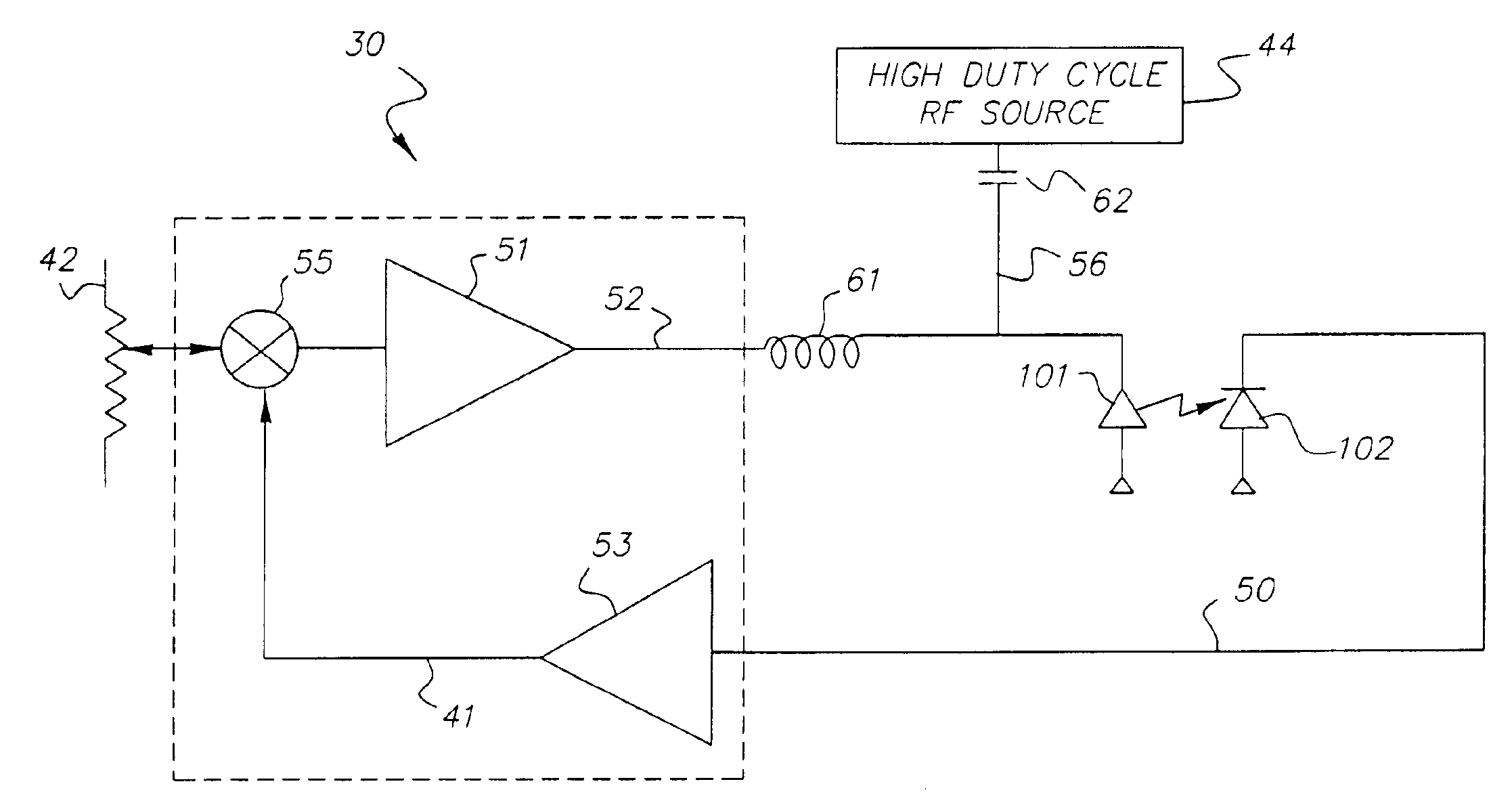
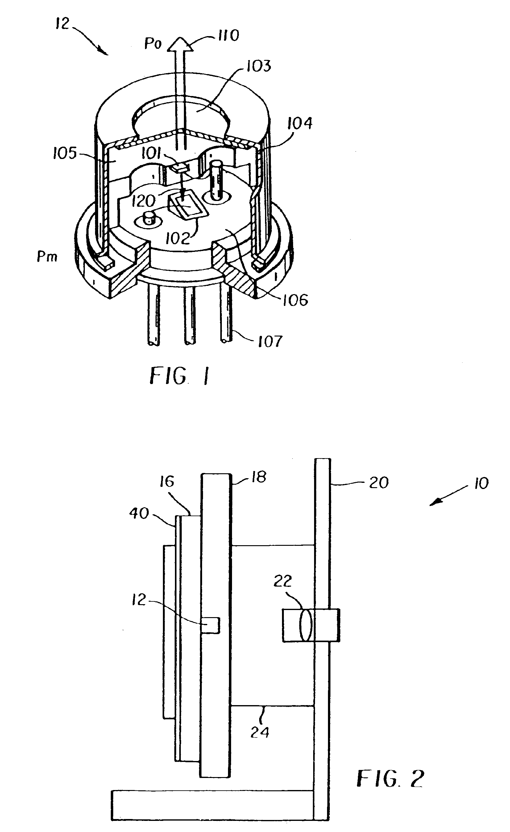
[0037]FIG. 1 shows a semiconductor laser 12. Laser 12 is in a container defined by a cap 104 having an aperture 103 in a stem 106 and terminal 107. A semiconductor laser element 101 is mounted on a heatsink 105 with a light-emitting face on the side of aperture 103. A back facet photodiode 102 is fixed to stem 106 with a light receiving surface facing the semiconductor laser element 101. A laser beam 110 and a light power output (Po) is emitted from the semiconductor laser element 110 through aperture 103. At the same time, a monitor beam 120 with a light power output (Pm), at usually about 3% of Po, is emitted from the semiconductor laser element 101 toward the photodiode 102....


PUM


Abstract

A system and method of stabilizing laser output levels includes a laser (10), an injection circuit for injecting a radio frequency waveform, and a control circuit for energizing and stabilizing the laser. The radio frequency waveform injected by the injection circuit has a high duty cycle to maintain high output power while providing a stable multimode spectrum. A back facet photodiode sensor (102) detects radiation emitted from a back facet semiconductor laser (101) and provides a feedback signal to the control circuit (41) for maintaining the laser output power. The response of the photodiode is not fast enough to track intensity variations due to the RF waveform, and thus provides feedback to the control circuit (41) only when there is a substantial need to adjust laser power.

Description

CROSS REFERENCE TO RELATED APPLICATIONS[0001]This is a Continuation-in-Part of U.S. patent application Ser. No. 09 / 788,747, filed Feb. 20, 2001 now abandoned, entitled SYSTEM AND METHOD FOR IMPROVING LASER POWER AND STABILIZATION USING HIGH DUTY CYCLE RADIO FREQUENCY INJECTION, by Roddy et al.FIELD OF THE INVENTION[0002]This invention relates in general to stabilized semiconductor lasers for imaging applications and in particular, to a high duty cycle radio frequency waveform injected into a semiconductor laser with a back facet closed loop control circuit.BACKGROUND OF THE INVENTION[0003]In many imaging applications, it is often desirable to have an inexpensive semiconductor laser device that provides constant wavelength and power output, as well as low noise. In one type of laser raster printing system, a photosensitive media is placed on a drum and is written to by a semiconductor laser. A light beam from the laser is typically deflected from a polygon or galvanometer, and focuse...

Claims


Application Information

Patent Timeline
IPC IPC(8): H01S3/10H01S5/022H01S5/062H01S5/042H01S5/0683H01S5/0687
CPCH01S5/06832H01S5/02212H01S5/0427
Inventor RODDY, JAMES E.MARKIS, WILLIAM R.
Owner IMAX THEATERS INT
Why Eureka
Try Eureka