Medical laser apparatus

a laser and laser tube technology, applied in the field of medical laser tubes, can solve the problems of increasing the size of the apparatus, short life of the laser tube, and large electric power requirements, and achieve the effects of reducing size, low electric power requirements, and long li

Inactive Publication Date: 2006-02-21
NIDEK CO LTD
View PDF16 Cites 6 Cited by
  • Summary
  • Abstract
  • Description
  • Claims
  • Application Information

AI Technical Summary

Benefits of technology

[0007]The present invention has been made in view of the above circumstances and has an object to overcome the above problems and thus provide a medical laser apparatus which c

Problems solved by technology

The apparatuses using the krypton laser or the dye laser have many disadvantages; a short life of a laser tube, large electric power requirements, and an increase in apparatus size.
On the other

Method used


Image

  • Medical laser apparatus
  • Medical laser apparatus
  • Medical laser apparatus

Examples


first embodiment

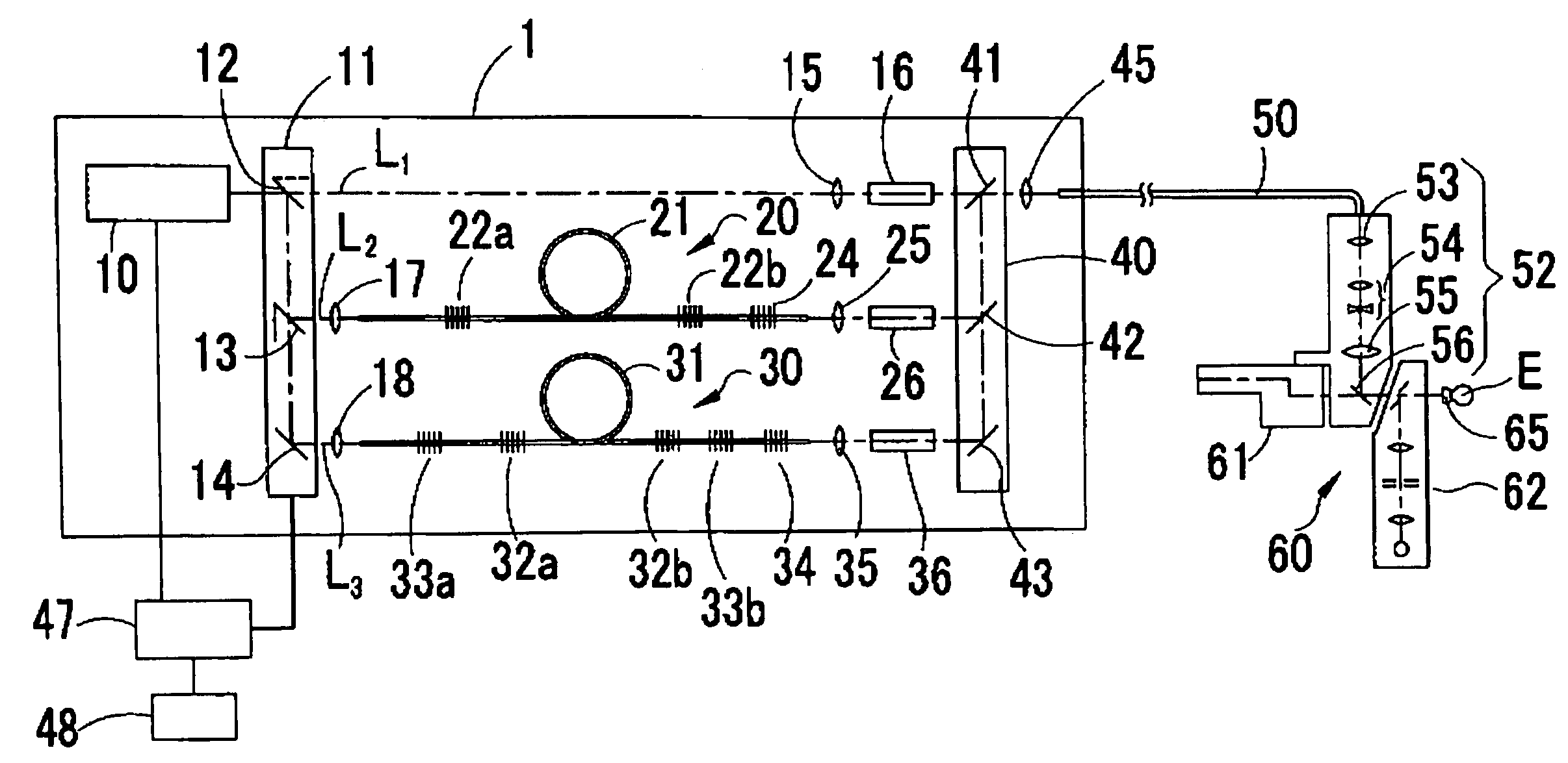
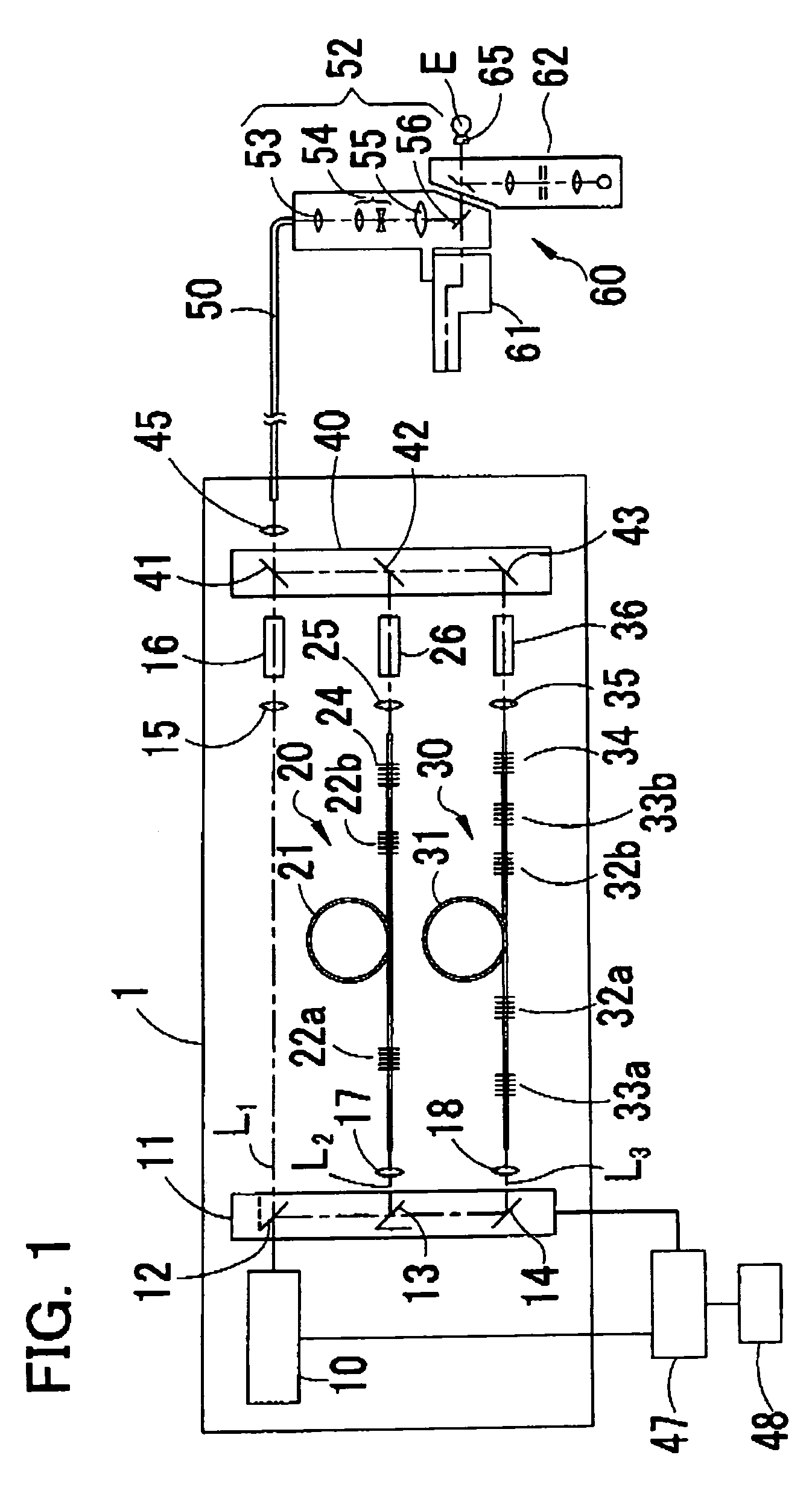
[0017]A detailed description of preferred embodiments of the present invention will now be given referring to the accompanying drawings. FIG. 1 is a schematic structural view of a laser apparatus for an ophthalmic treatment in a

[0018]In FIG. 1, a laser oscillator 1 which emits a laser beam is internally provided with a laser oscillating source 10 which emits a linearly polarized infrared beam. This laser oscillating source 10 is for example an Nd:YAG laser which is a laser diode pump and emits a fundamental-wave infrared beam of a wavelength λ1 (approx. 1064 nm). An input switching unit 11 selectively directs the beam of the wavelength λ1 (hereinafter, referred to as “λ1-beam”) emitted from the laser oscillating source 10 to a first optical path L1, a second optical path L2, or a third optical path L3. This input switching unit 11 is constructed of for example a mirror 12 placed in the optical path L1 and mirrors 13 and 14 placed in order in an optical path formed in a reflecting di...

fourth embodiment

[0051]In the laser oscillator 1 in the fourth embodiment, each optical element in the optical paths of the beams outputted from the laser oscillating source 10 and inputted into the optical fiber 50 is connected to one another by the fiber optical systems. Accordingly, the alignment problem of each optical element can be reduced and a reliable laser apparatus can be realized. It is more effective if a fiber laser such as a Yb fiber laser is used as the laser oscillating source 10.

[0052]In the fourth embodiment, as in the case of the first and third embodiments, the Raman wavelength shifter 160 and the Raman wavelength shifter 170 may be used partially or entirely in common.

[0053]The laser apparatus for an ophthalmic treatments is explained in the above embodiments, but the present invention can be applied to a laser apparatus for a dermatological treatment.


PUM


Abstract

A medical laser apparatus comprises: a solid laser oscillating source which emits a beam of a wavelength λ1 in an infrared region of approx. 1040 nm to approx. 1080 nm; a first fiber-based Raman shifter including a first Raman fiber which generates, when receives the λ1-beam from the laser oscillating source, a first-order Stokes beam of a wavelength λ2 different from the wavelength λ1 by stimulated Raman scattering, the first Raman fiber being formed with a pair of fiber Bragg gratings which forms a resonator for the λ2-beam; a first nonlinear crystal which wavelength-converts the λ2-beam outputted from the first Raman wavelength shifter to a second harmonic beam of a wavelength λ2′ in an orange region of approx. 580 nm to approx. 600 nm; and a light guiding optical system which guides the λ2′-beam to a treatment part.

Description

BACKGROUND OF THE INVENTION[0001]1. Field of the Invention[0002]The present invention relates to a medical laser apparatus which is used in an ophthalmic hospital and others.[0003]2. Description of Related Art[0004]As medical laser apparatuses (e.g., for ophthalmic treatments), there have been known apparatus using a krypton laser, a dye laser, a frequency doubled Nd:YAG laser which is a solid laser, or the like. For example, the krypton laser can generate green laser beams of wavelengths of approx. 520 nm and approx. 530 nm, a yellow laser beam of a wavelength of approx. 568 nm, and a red laser beam of a wavelength of approx. 647 nm. The dye laser can generate yellow to red laser beams of wavelengths of approx. 575 nm to approx. 630 nm. The frequency doubled Nd:YAG laser can generate second harmonics, that is, a green laser beam of a wavelength of approx. 532 nm, a yellow laser beam of a wavelength of approx. 561 nm, and a red laser beam of a wavelength of approx, 659 nm.[0005]For ...

Claims


Application Information

Patent Timeline
IPC IPC(8): H01S3/30A61B18/20G02F1/35A61B18/22A61F9/007A61N5/06G02F1/37H01S3/067
CPCA61B18/22G02F1/37A61B2018/2065H01S3/302H01S3/0675H01S3/094061H01S3/1655A61F9/00823A61F9/00821
Inventor SHARMA, LALIT B.HAYASHI, KENICHI
Owner NIDEK CO LTD
Why Eureka
Try Eureka