Single pole type recording head with tapered edges

a single-pole type, tapered edge technology, applied in the direction of magnetic recording heads, data recording, instruments, etc., can solve the problems of hindering the improvement of track density, reducing the length of bits to be recorded, and the area recording density of existing in-plane recording systems cannot be increased, so as to improve thermal fluctuation resistance, prevent a decrease in magnetic field intensity, and the effect of high area recording density

Inactive Publication Date: 2006-02-28
HITACHI GLOBAL STORAGE TECH JAPAN LTD +1
View PDF13 Cites 54 Cited by
  • Summary
  • Abstract
  • Description
  • Claims
  • Application Information

AI Technical Summary

Benefits of technology

[0030]By manufacturing the main pole as described above, it may be possible to provide a single magnetic pole type recording head that does not erase data on adjacent tracks, while preventing a decrease in the magnetic field intensity. Further, it may be possible to provide a magnetic recording apparatus with a higher area recording density that is superior in thermal fluctuation resistance to conventional apparatuses. This apparatus may be used in a longitudinal recording system by mounting a double layered perpendicular medium having a soft magnetic underlayer and a single pole type recording head.

Problems solved by technology

However, the area recording density of existing in-plane recording systems can not be increased as the length of bits to be recorded is decreased because of thermal fluctuation in the magnetization of the media.
These side recording tracks reduce cross talk with adjacent recording tracks, however, they hinder the improvement of the track density which therefore hinders any improvement in the area recording density.
However, when a polishing method such as chemical mechanical polishing (CMP) is used, it is difficult to control the layer thickness which hinders the accuracy of the layer thickness.
This inaccuracy scatters the layer thickness of the main pole, thereby causing scattering in the intensity of the magnetic field from the main pole.

Method used


Image

  • Single pole type recording head with tapered edges
  • Single pole type recording head with tapered edges
  • Single pole type recording head with tapered edges

Examples


first exemplary embodiment

[First Exemplary Embodiment]

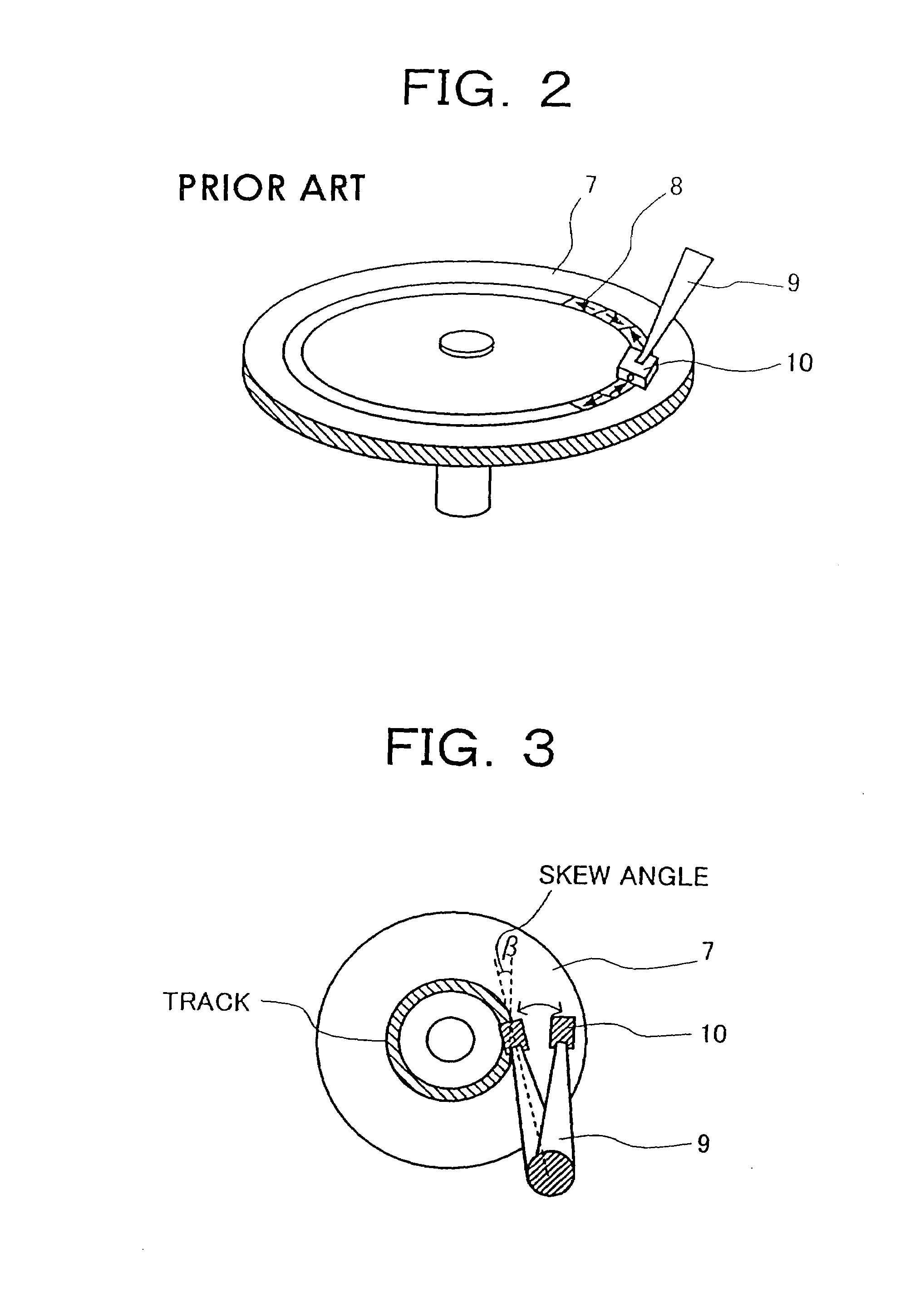
[0057]FIG. 2 is a schematic view of a magnetic disk storage apparatus according to a preferred embodiment of the present invention illustrating the relationship between a magnetic disk 7 and a magnetic head 10 (FIG. 2 is not to scale). The magnetic disk storage apparatus has a rotating magnetic disk 7 and a magnetic head 10 secured to one end of a support 9. The apparatus reads and writes magnetization signals 8 on the magnetic disk 7. FIG. 3 is a schematic view when the magnetic head 10 is moved on the rotating magnetic disk 7 by swinging a support 9 (not to scale). In this case, a skew angle β is formed between the magnetic head 20 supported by support 9 and a tangent drawn to a track on the magnetic disk 7. The skew angle β changes as the head is rotated across various tracks (concentric circles on the disk 7) and is typically within a range of about ±30°.

[0058]FIG. 4 is a schematic view showing a magnetic head for perpendicular recording according to ...

second exemplary embodiment

[Second Exemplary Embodiment]

[0066]FIG. 12 is a schematic view for a presently preferred manufacturing method according to this invention (not to scale). FIG. 12A shows a step of forming a resist pattern 24 on an inorganic insulating layer 23. Al2O3 may be preferred for the inorganic insulating layer, but SiC, AlN, Ta2O5, TiC, TiO2, SiO2 and other materials may also be used. The resist pattern 24 is exposed using a KrF excimer laser stepper. As the resist 24, a positive resist such as TDUR-P201 manufactured by Tokyo Ohka Kogyo Co., Ltd. may be used. When a resist of 0.7 μm thickness is formed, a 0.2 μm size can be resolved.

[0067]FIG. 12B shows a step of etching the inorganic insulating layer 23 by using the resist 24 as a mask. When Al2O3 is used for the resist 24, BCl3 or a gas mixture of BCl3 and Cl2 may be used as an etching gas. In addition, when AlN is used, the chlorine type gas described above is preferred for etching. In a case where easily etchable Ta2O5, TiC, TiO2, SiO2, S...

third exemplary embodiment

[Third Exemplary Embodiment]

[0074]FIG. 13 is an alternate schematic view of a medium-head system for a magnetic disk apparatus according to a preferred embodiment of the present invention (not to scale). As briefly described above, the magnetic disk storage apparatus writes and reads magnetization signals on a magnetic disk 7 using a magnetic head 28 attached to a slider 10 fixed to one end of a suspension arm 9. The magnetic head 28 moves in the radial direction of the disk 7 (seeking operation) by the swinging operation of the suspension arm 9. Also as described above, a skew angle β (of approximately ±30°) is set as shown in FIG. 13.

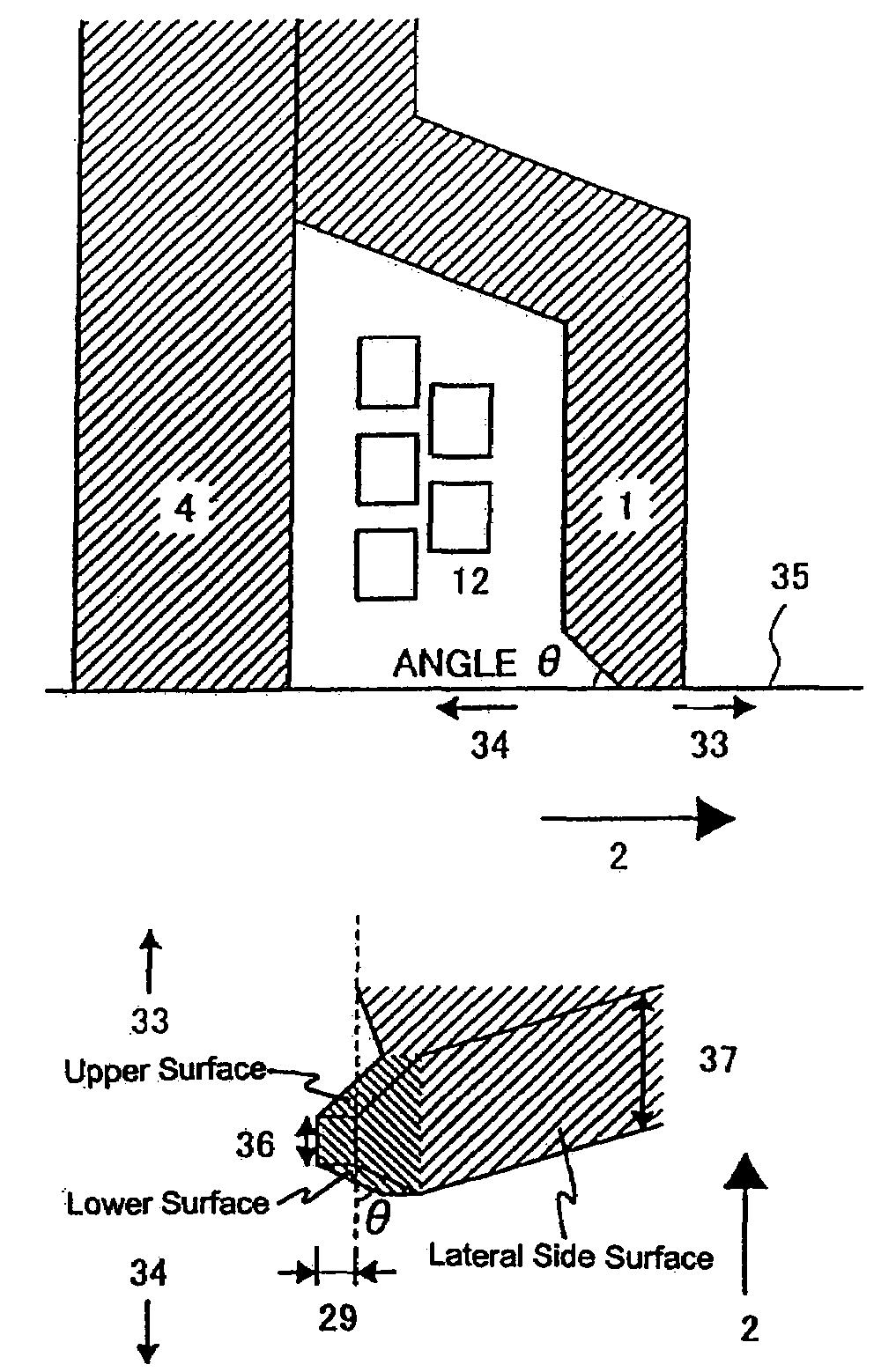
[0075]FIG. 14 is a schematic view for the relation between the writing / reading head for perpendicular recording and a magnetic disk 7. The perpendicular writing / reading head comprises a writing head part 30 and a reading head part 31. The writing head is a single pole type recording head and the reading head has a structure in which a reading device i...


PUM

PropertyMeasurementUnit
angleaaaaaaaaaa
angleaaaaaaaaaa
thicknessaaaaaaaaaa

Abstract

A magnetic head for perpendicular recording without writing from the lateral sides of a mains pole and without erasing data on adjacent tracks. A magnetic disk storage apparatus using the magnetic head. The lateral side of the main pole of a magnetic head for perpendicular recording may have an inverted tapered shape obtained by forming a groove as a track portion to an inorganic insulating layer and then forming a magnetic layer and then flattening the upper surface. A leading edge, a trailing edge, or both lateral edges of the magnetic head may be tapered. The taper may be either smooth and linear or curved in profile.

Description

PRIORITY TO FOREIGN APPLICATIONS[0001]This application is a Divisional of nonprovisional application Ser. No. 09 / 920,648 filed Aug. 3, 2001 now U.S. Pat. No. 6,710,973. Priority is claimed based on U.S. application Ser. No. 09 / 920,648 filed Aug. 3, 2001, which claims the priority of Japanese applications 2000-286842 filed on Sep. 18, 2000 and 2000-328405 filed on Oct. 23, 2000.BACKGROUND OF THE INVENTION[0002]1. Field of the Invention[0003]This invention concerns a thin layer magnetic head used for recording and reproduction, for example, in a magnetic disk storage apparatus and a magnetic disk storage apparatus mounting the magnetic head.[0004]2. Description of the Background[0005]In a magnetic disk storage apparatus, data on the recording media is read and written by a magnetic head. In order to increase the recording capacity per unit area of the magnetic disk, it is necessary to increase the area recording density. However, the area recording density of existing in-plane recordi...

Claims


Application Information

Patent Timeline
Patent Type & Authority Patents(United States)
IPC IPC(8): G11B5/127G11B5/012
CPCG11B5/012G11B5/1278Y10S977/935Y10S977/934
Inventor OKADA, TOMOHIRONISHIDA, YASUTAKAMICHIZUKI, MASAFUMITAKANO, HISASHI
Owner HITACHI GLOBAL STORAGE TECH JAPAN LTD
Why Eureka
Try Eureka