[0007]In a presently preferred embodiment, the
balloon catheter is a
stent delivery
catheter, with a
stent mounted on the balloon for delivering and implanting the
stent in a patient's body lumen, although the
catheter balloon of the invention is suitable for use in a variety of balloon catheters, which in alternative embodiments of the invention include coronary and
peripheral dilatation catheters,
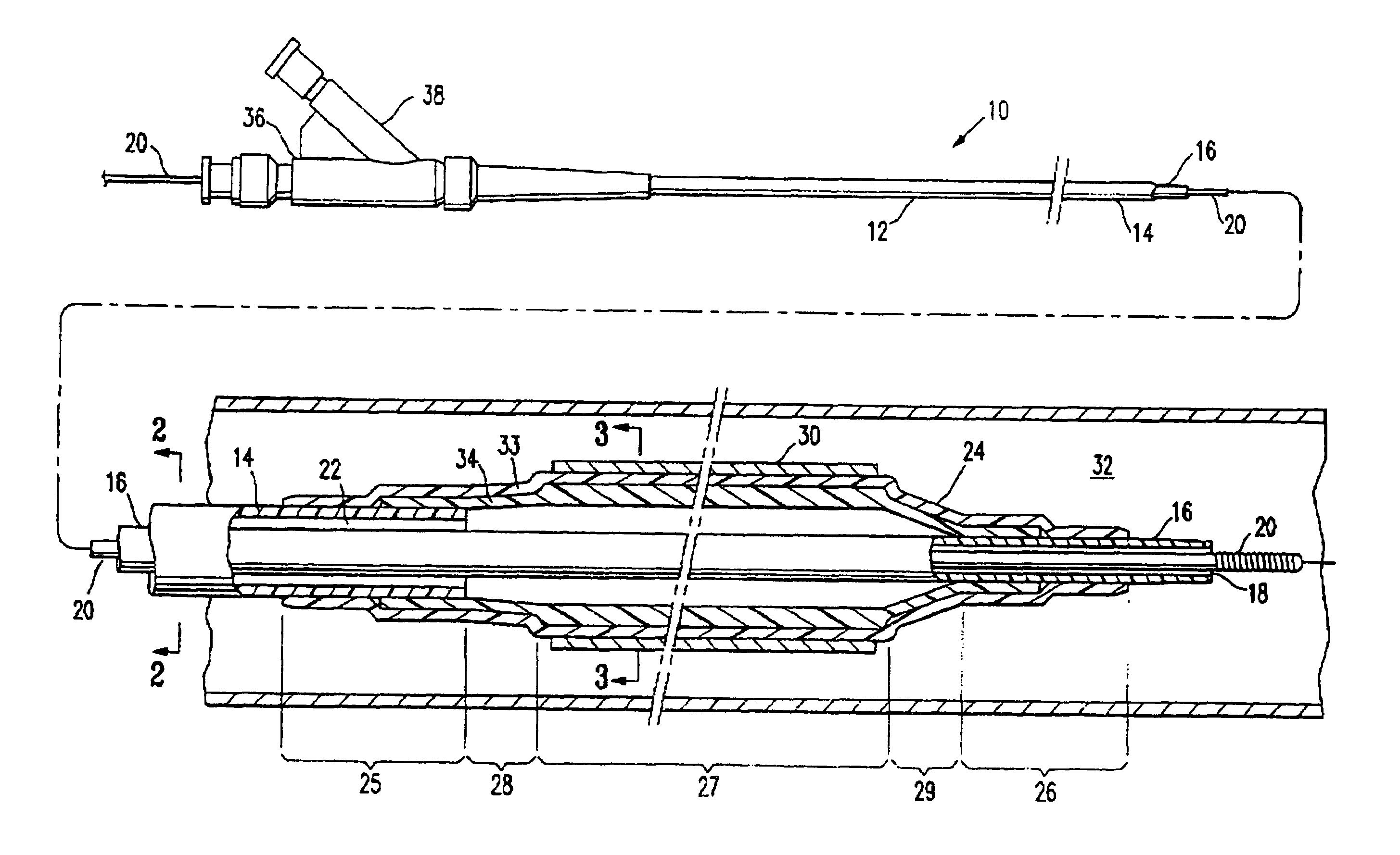
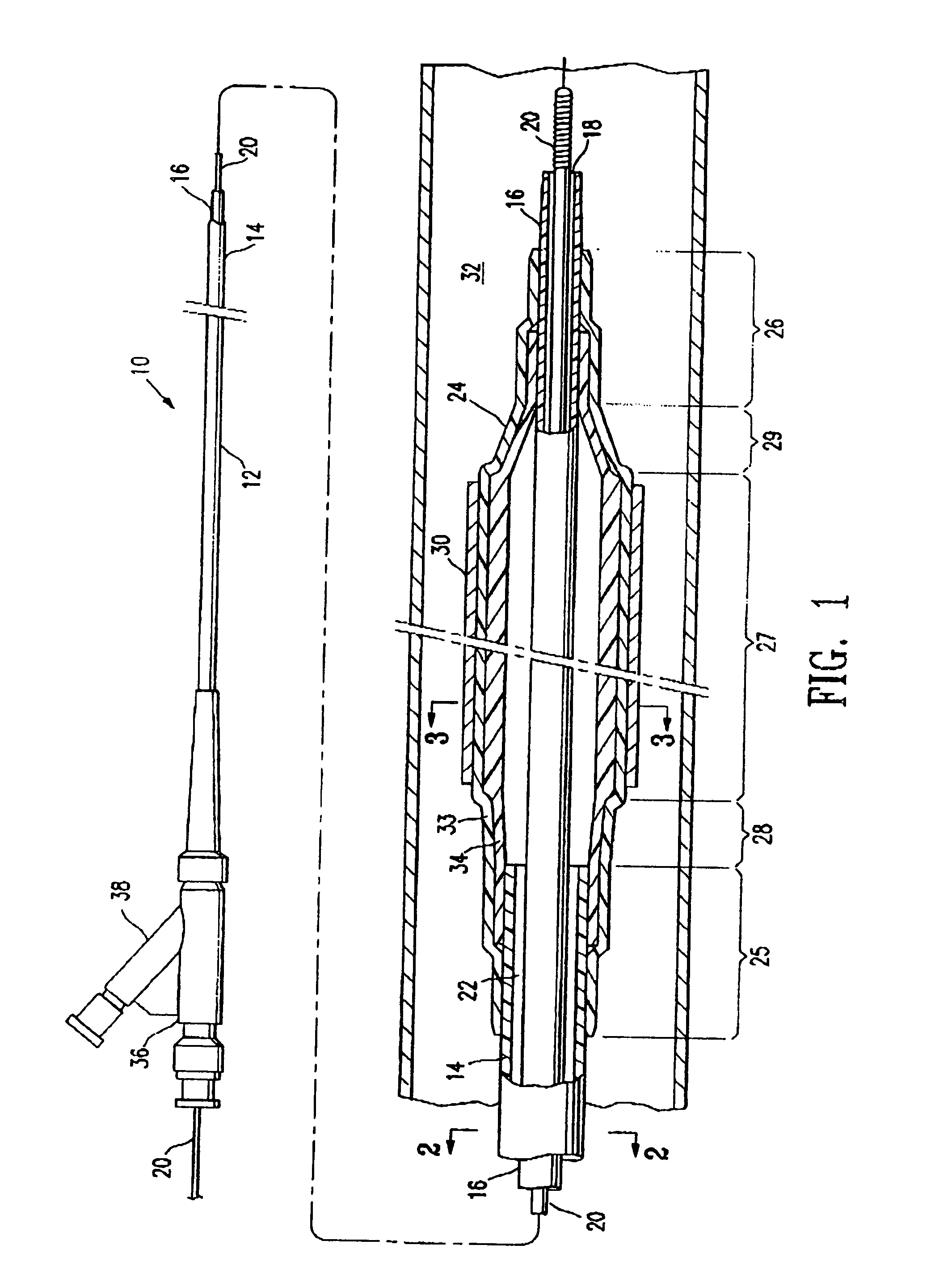
drug delivery catheters, and the like. A balloon catheter of the invention generally comprises an elongated shaft having a proximal end, a distal end, and at least one lumen, and a balloon on a distal shaft section with an interior in fluid communication with the at least one lumen of the shaft. The balloon has a proximal skirt section bonded to the shaft, a distal skirt section bonded to the shaft, and an
inflatable section therebetween. The balloon has a noninflated configuration (i.e., prior to inflation of the balloon to the working
diameter) which inflates to an inflated configuration within the
working pressure range. After being inflated, the balloon in the inflated configuration can be deflated to a deflated configuration. The
inflatable section of the balloon comprises a central working length section configured to perform a procedure such as dilating a
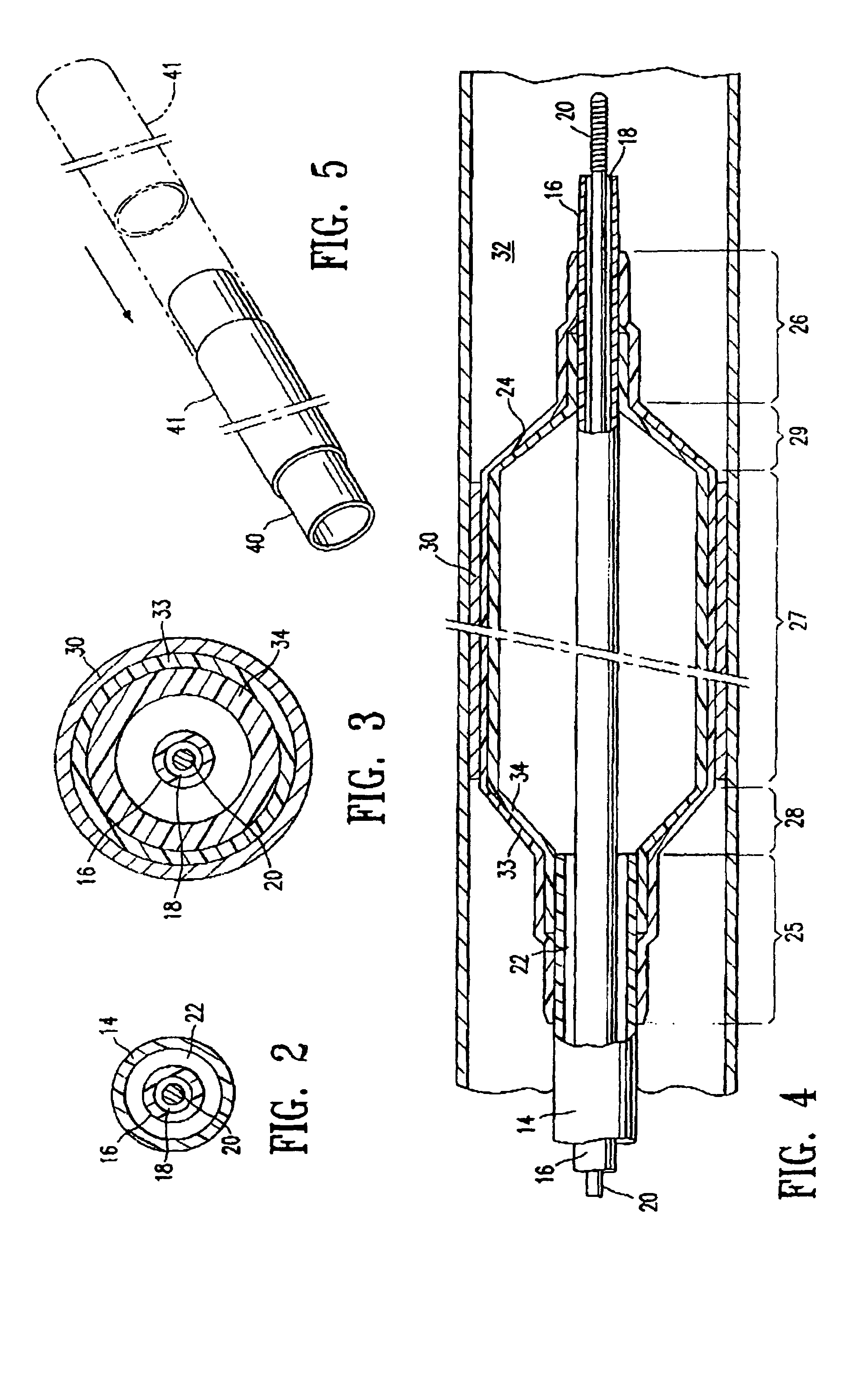
stenosis or expanding a stent, a proximal tapered section between the proximal skirt section and the working length section, and a distal tapered section between the distal skirt section and the working length section. In a presently preferred embodiment, the wall thickness of the balloon second layer along the working length section is greater than the wall thickness of the second layer along at least one of the proximal and distal tapered sections of the balloon, and most preferably is greater than the wall thickness of the second layer along the proximal and distal tapered sections and / or the proximal and distal skirt sections of the balloon. The thickened wall portion of the balloon, resulting from the increased wall thickness of the second layer along the working length section, increases the strength of the balloon to thereby allow for expansion of the balloon to relatively large working diameters (e.g., greater than 3.0 mm), without resulting in disadvantageously thick sections of the balloon on either end of the working length section. Consequently, the stiffness of the distal end of the catheter at the balloon location is minimized. In a presently preferred embodiment, the wall thickness of the second layer of the balloon is greater than the wall thickness of the second layer along the proximal and / or distal tapered sections from the proximal to the distal end of the tapered section of the balloon (i.e., along the entire length of the proximal and distal tapered sections of the balloon).
[0008]In a presently preferred embodiment, the polymeric material forming the first layer of the balloon is a porous polymeric material such as
expanded polytetrafluoroethylene (ePTFE), including ePTFE available from Zeus, Atrium Medical, Inertech, and IPE, and typically having an initial
porosity of at least about 60%. However, a variety of suitable porous materials may be used including an ultra high molecular weight
polyolefin such as
ultra high molecular weight polyethylene, porous
polyethylene, porous
polypropylene, and porous
polyurethane. In one embodiment, the porous material has a node and
fibril microstructure. The node and
fibril microstructure, when present, is produced in the material using conventional methods. ePTFE and
ultra high molecular weight polyethylene (also referred to as “expanded
ultra high molecular weight polyethylene”) typically have a node and
fibril microstructure, and are not melt extrudable. However, a variety of suitable polymeric materials can be used in the method of the invention including conventional catheter balloon materials which are melt extrudable. Typically, ePTFE is formed into a tubular balloon layer by bonding wrapped
layers of the polymeric material together to form a tubular member, and not by conventional balloon
blow molding. Although discussed primarily in terms of the embodiment in which the first layer of the balloon comprises ePTFE, it should be understood that a variety of suitable polymers may be used for the first layer. The second layer of the balloon prevents or inhibits inflation fluid from leaking out of the balloon interior through the porous polymeric material of the first layer, and is typically an inner layer or liner relative to the first layer of the balloon.
[0009]In a method of making a balloon of the invention, the second layer is formed of first and second sublayers of polymeric material placed one on top of the other, and typically fused together, to form the second layer having a thickened wall portion. However, a variety of methods can alternatively be used to make the balloon of the invention having a thickened wall portion. Forming the second layer by combining polymeric sublayers together to form the thickened polymeric wall portion is generally preferred over a method in which the ends of the second layer are thinned, as for example by
necking or mechanically removing material therefrom, due to the ability to increase the wall thickness more precisely and without a decrease in the strength of the layer compared to the other methods.
[0010]The balloon catheter of the invention has excellent flexibility and improved balloon strength, with a low profile in the noninflated configuration, due to the configuration of the thickened wall portion of the balloon. Consequently, the catheter has excellent trackability (ability to track along the guidewire), and crossability (ability to cross a tight region of the
blood vessel). These and other advantages of the invention will become more apparent from the following detailed description and accompanying exemplary drawings.

