Fractal antenna ground counterpoise, ground planes, and loading elements and microstrip patch antennas with fractal structure

Inactive Publication Date: 2006-03-28
FRACTAL ANTENNA SYST
View PDF23 Cites 88 Cited by
  • Summary
  • Abstract
  • Description
  • Claims
  • Application Information

AI Technical Summary

Benefits of technology

[0027]In one aspect, the present invention provides an antenna with a ground plane or ground counterpoise system that has at least one element whose shape, at least is part, is substantially a deterministic fractal of iteration order N≧1. (The term “ground counterpoise” will be understood to include a ground plane, and/or at least one ground element.) Using fractal geometry, the antenna ground counterpoise has a self-similar structure resulting from the repetition of a design or motif (or “generator”) that is replicated using rotation, and/or translation,

Problems solved by technology

The unfortunate result is that antenna design has far too long concentrated on the ease of antenna construction, rather than on the underlying electromagnetics.
Experience has long demonstrated that small sized antennas, including loops, do not work well, one reason being that radiation resistance (“R”) decreases sharply when the antenna size is shortened.
Ohmic losses can be minimized using impedance matching networks, which can be expensive and difficult to use.
Unfortunately, radiation resistance R can all too readily be less than 1Ω for a small loop antenna.
Kraus' early research and conclusions that small-sized antennas will exhibit a relatively large ohmic resistance O and a relatively small radiation resistance R, such that resultant low efficiency defeats the use of the small antenna have been widely accepted.
But Kim and Jaggard did not apply a fractal condition to the antenna elements, and test results were not necessarily better than any other techniques, including a totally random spreading of antenna elements.
However, log periodic antennas do not utilize th

Method used


Image

  • Fractal antenna ground counterpoise, ground planes, and loading elements and microstrip patch antennas with fractal structure
  • Fractal antenna ground counterpoise, ground planes, and loading elements and microstrip patch antennas with fractal structure
  • Fractal antenna ground counterpoise, ground planes, and loading elements and microstrip patch antennas with fractal structure

Examples


Embodiment Construction

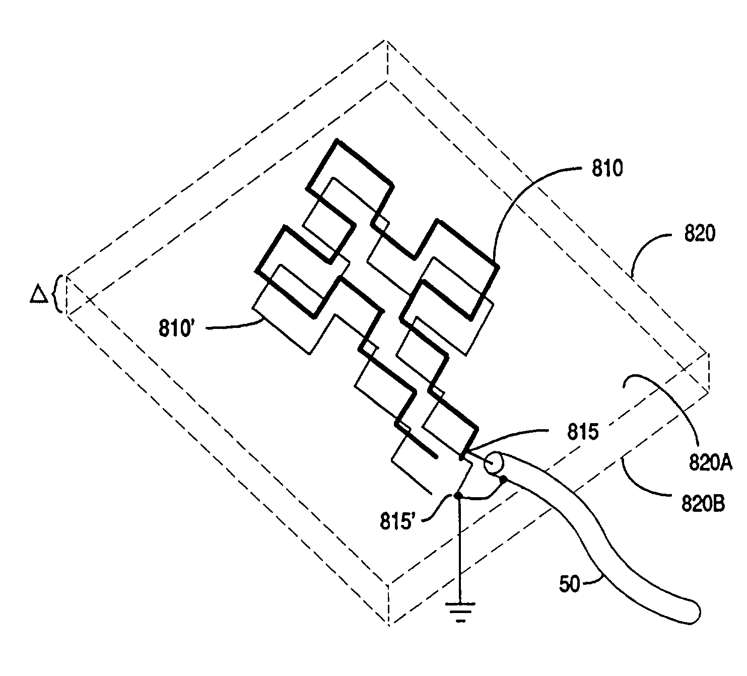
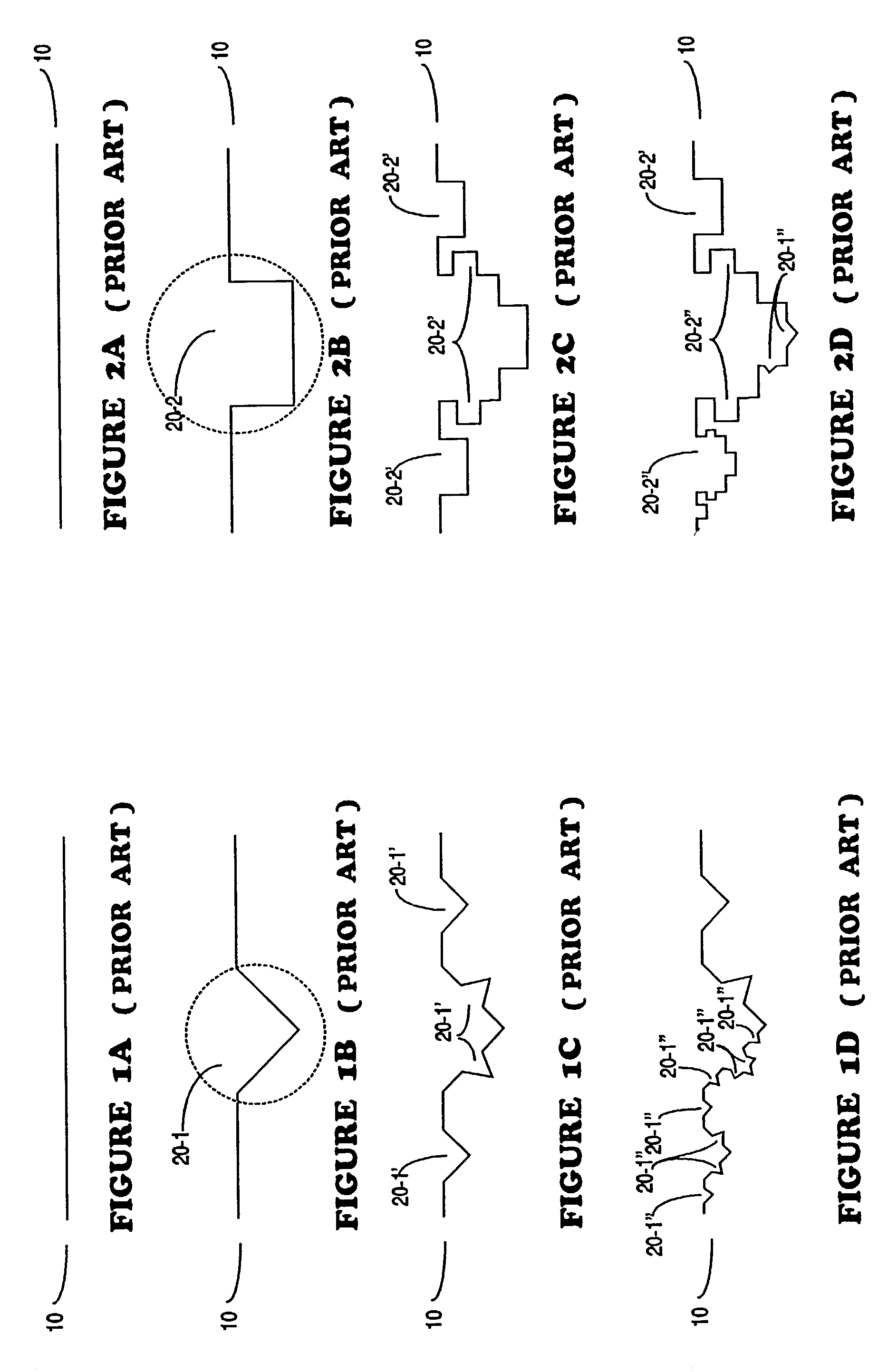
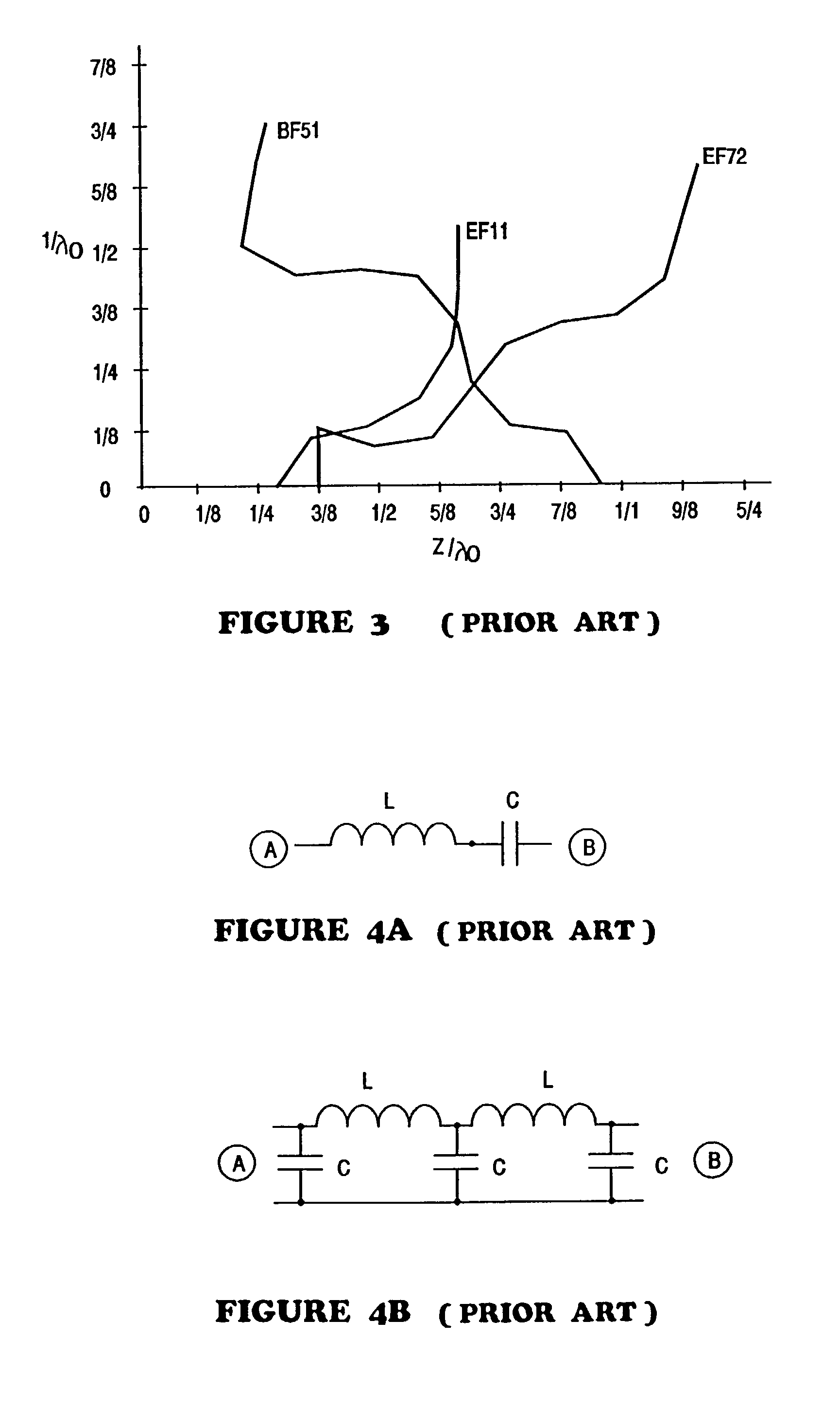
[0100]In overview, in one aspect, the present invention provides an antenna system with a fractal ground counterpoise, e.g., a counterpoise and / or ground plane and / or ground element having at least one element whose shape, at least is part, is substantially a fractal of iteration order N≧1. The resultant antenna is smaller than its Euclidean counterpart, provides close to 50Ω termination impedance, exhibits at least as much gain and more frequencies of resonance than its Euclidean counterpart, including non-harmonically related frequencies of resonance, exhibits a low Q and resultant good bandwidth, acceptable SWR, a radiation impedance that is frequency dependent, and high efficiencies.

[0101]In another aspect, the present invention provides a microstrip patch antenna with at least one element whose shape, at least is part, is substantially a fractal of iteration order N≧1. The resultant antenna is smaller than its Euclidean counterpart, provides close to 50Ω termination impedance, ...


PUM


Abstract

An antenna system includes a fractalized element that may be a ground counterpoise, a top-hat located load assembly, or a microstrip patch antenna having at least one element whose physical shape is at least partially defined as a first or higher iteration deterministic fractal. The resultant fractal element may rely upon an opening angle for performance, and is more compact than non-Euclidean ground counterpoise elements or the like. A vertical antenna system includes a vertical element that may also be a fractal, and a vertical antenna can include vertically spaced-apart fractal conductive and passive elements, and at least one fractal ground element. Various antenna configurations may be fabricated on opposite surfaces of a substrate, including a flexible substrate, and may be tuned by rotating elements relative to each other, and/or by varying the spaced-apart distance therebetween. Fractalized ground counterpoise elements and/or microstrip patch antenna systems may be fabricated on a flexible printed circuit substrate, and/or placed within the support mount of a cellular telephone car antenna.

Description

RELATION TO PREVIOUSLY FILED PATENT APPLICATIONS[0001]This application is a continuing application from applicant's co-pending patent application Ser. No. 09 / 677,645 entitled Fractal Antenna Ground Counterpoise, Ground Planes, And Loading Elements And Microstrip Patch Antennas With Fractal Structure, filed 3 Oct. 2000, which in turn is a continuing application of application Ser. No. 08 / 967,375 entitled Fractal Antenna Ground Counterpoise, Ground Planes, And Loading Elements, filed 7 Nov. 1997, and from applicant's patent application Ser. No. 08 / 965,914 entitled Microstrip Patch Antennas With Fractal Structure, filed 7 Nov. 1997, issued as U.S. Pat. No. 6,127,977 (3 Oct. 2000). Applicant incorporate by reference herein his U.S. Pat. No. 6,104,349 (15 Aug. 2000) entitled Tuning Fractal Antennas and Fractal Resonators.FIELD OF THE INVENTION[0002]The present invention relates to antennas and resonators, and microstrip patch antennas, and specifically to designing and tuning non-Euclidi...

Claims


Application Information

Patent Timeline
IPC IPC(8): H01Q1/38H01Q1/24H01Q1/36H01Q1/44H01Q9/04H01Q21/20H01Q21/28
CPCH01Q1/243H01Q1/246H01Q1/36H01Q1/38H01Q1/44H01Q1/48H01Q5/371H01Q9/40H01Q21/20H01Q21/205H01Q21/28H01Q15/0093H01Q5/357H01Q9/0407
Inventor COHEN, NATHAN
Owner FRACTAL ANTENNA SYST
Why Eureka
Try Eureka