

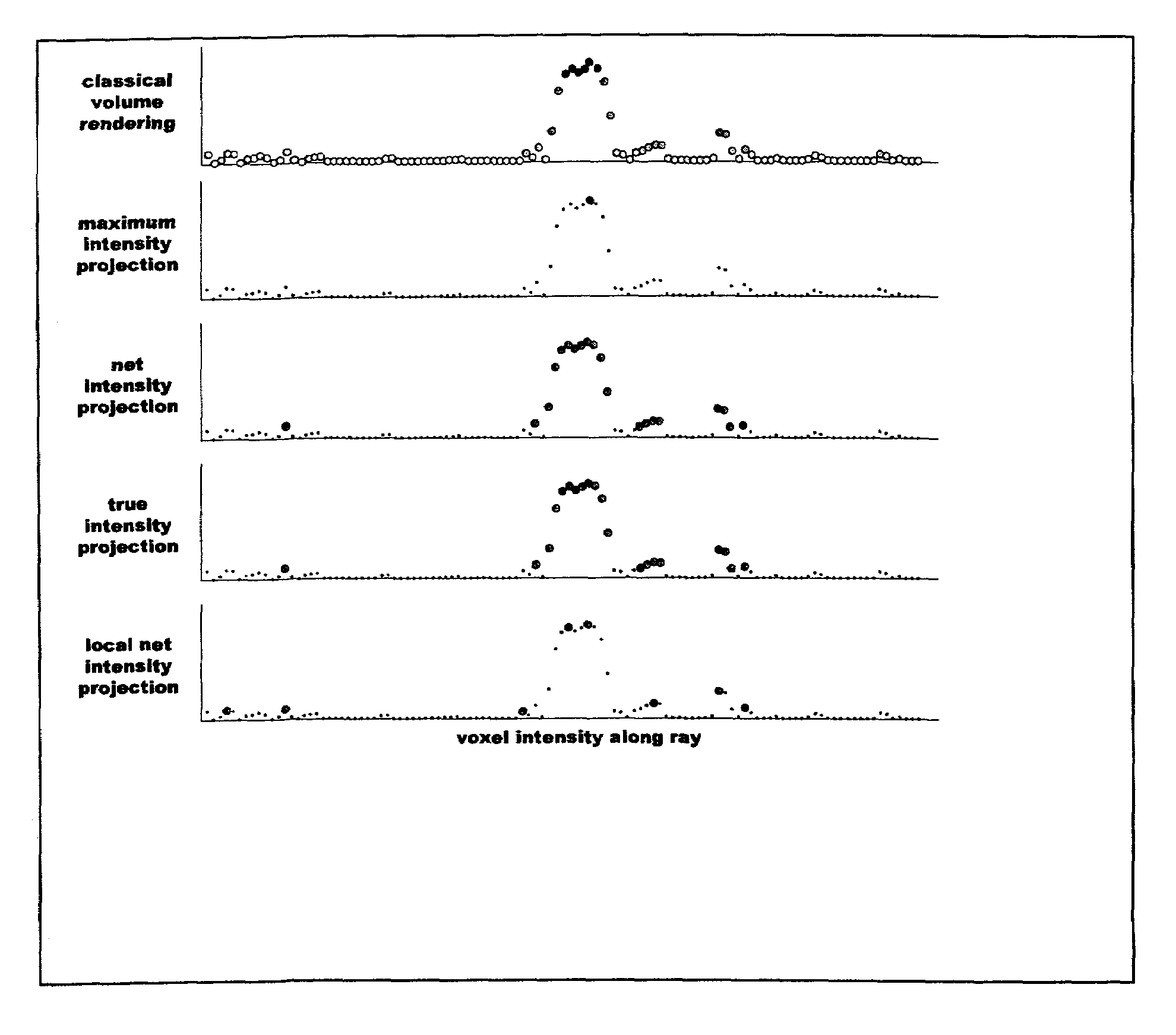
Translucent intensity projection imaging
a projection imaging and transparent technology, applied in the field of magnetic resonance imaging, magnetic resonance angiography (mra), computerized tomography, can solve the problems of unfavorable patient safety, unfavorable patient safety, and inability to accurately show the area where blood vessels are located, etc., to achieve superior results, remove unneeded effects, and high sensitivity
- Summary
- Abstract
- Description
- Claims
- Application Information
AI Technical Summary
Benefits of technology
Problems solved by technology
Method used
Image


Examples
Embodiment Construction
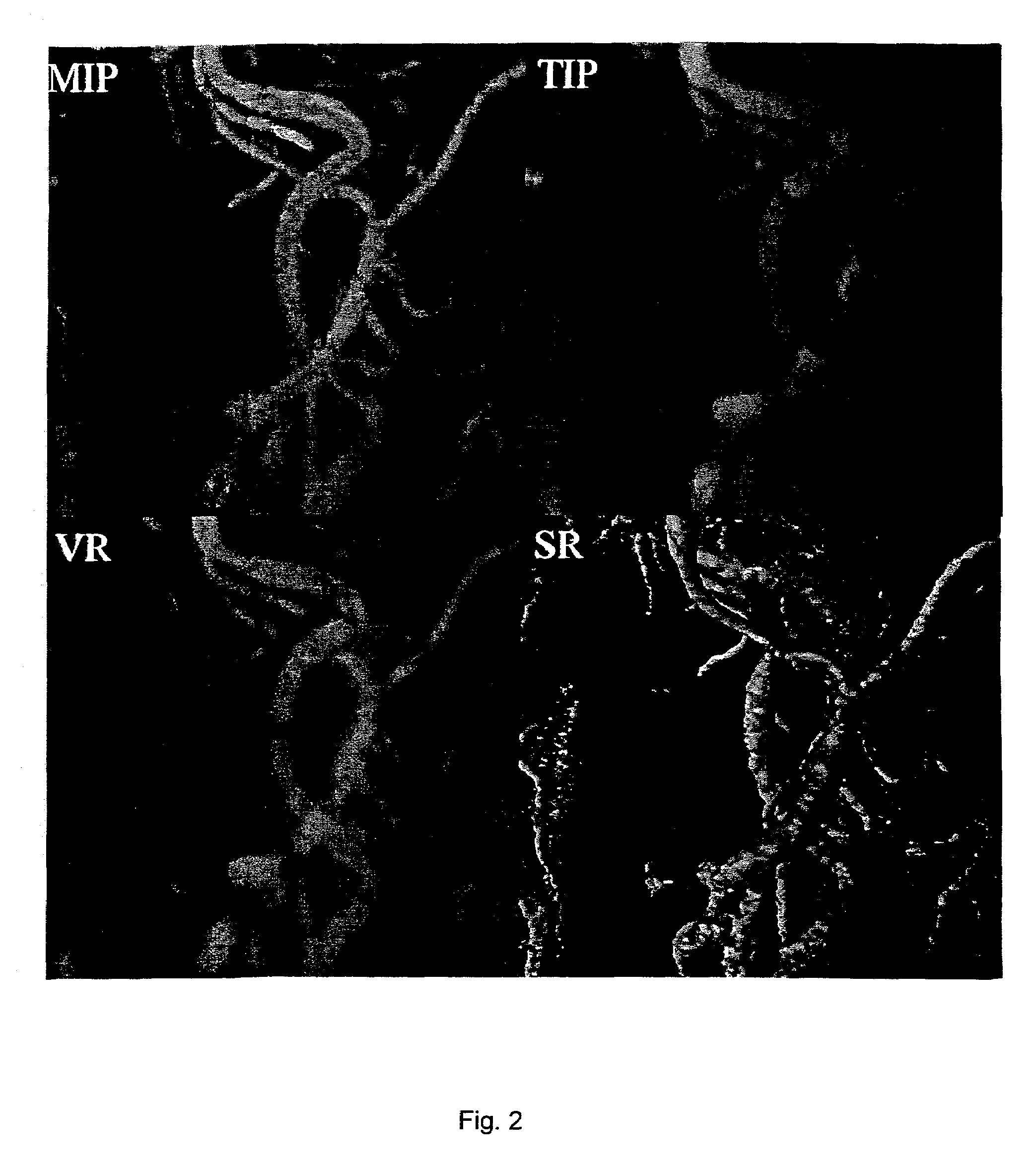
[0020]Features of different vessel visualization techniques can be assessed by processing an identical set of MRI data. In a specific and non-limiting example used here, a cardiovascular MR scanner, a Siemens Sonata 1.5T scanner, was used to obtain the data. A set of non-contrast data was obtained followed by a corresponding set after a bolus injection of 10–20 cc gadolinium contrast agent, using a conventional 3D contrast-MRA protocol. The scanner's gradient performance was considered sufficient (40 mT / m with 200 slew rate) to obtain breath-hold 3D contrast-MRA data in 18–25 seconds. The non-contrast MRA data set was used to mask the background signal from fat and other short-T1 structures, as is conventional, resulting in a corrected 3D data point set. An off-line computer was then used to calculate MIP and VR images using conventional software, and to calculate NIP and TIP images using methods described here. The calculated MIP, VR, NIP, and TIP images were transferred back to th...
PUM
 Abstract
Description
Claims
Application Information