Gas-gas-water treatment system for groundwater and soil remediation

a treatment system and groundwater technology, applied in water cleaning, survey, borehole/well accessories, etc., can solve the problems of uneconomical process, inability to deliver oxygen through the system, and inability to achieve the effect of biodegradation of leachate plumes

Inactive Publication Date: 2006-04-04
KERFOOT TECH
View PDF26 Cites 47 Cited by
  • Summary
  • Abstract
  • Description
  • Claims
  • Application Information

AI Technical Summary

Benefits of technology

[0015]The following systems and methods for removing contaminants from soil and an associated subsurface groundwater aquifer using microporous diffusers and duo-gas systems are particularly useful in that they promote extremely efficient removal of poorly biodegradable organics, particularly dissolved chlorinated solvents, without vacuum extraction, and wherein remediation occurs by destroying organic and hydrocarbon material in place without release of contaminating vapors.
[0028]Yet a further object is to obtain economy of operation by maximizing contact with the oxidant to achieve selective rapid extraction.

Problems solved by technology

However, Payne deals only with volatile contaminants.
Raymond has the disadvantage of failing to deliver oxygen through the system, and depends on a complicated process of hydrologic management of the subsurface which has rendered the process uneconomical.
Notwithstanding the teachings of Wang et al., Corey et al., and Wyness, there has not been shown a sparging system for remediating a site in a controlled manner of poorly biodegradable organics, employing oxidizing gas encapsulated in microbubbles generated from microporous diffusers matched to soil porosity pulsed in a wave form for even distribution through the substrate (aquifer structure) employing a co-reactant in the form of substrate material.
Further, the prior art fails to show matching of micron sized bubble formation with substrate material of a selected aquifer or to show the beneficial effect of uniform distribution of sized bubbles through such a formation by means of a pulsed wave form without fracturing said substrate.

Method used


Image

  • Gas-gas-water treatment system for groundwater and soil remediation
  • Gas-gas-water treatment system for groundwater and soil remediation
  • Gas-gas-water treatment system for groundwater and soil remediation

Examples


Embodiment Construction

.

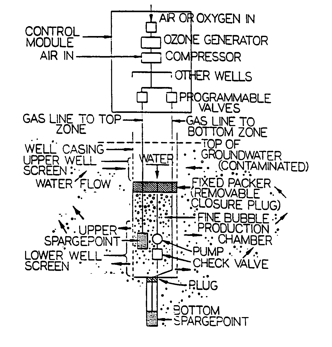
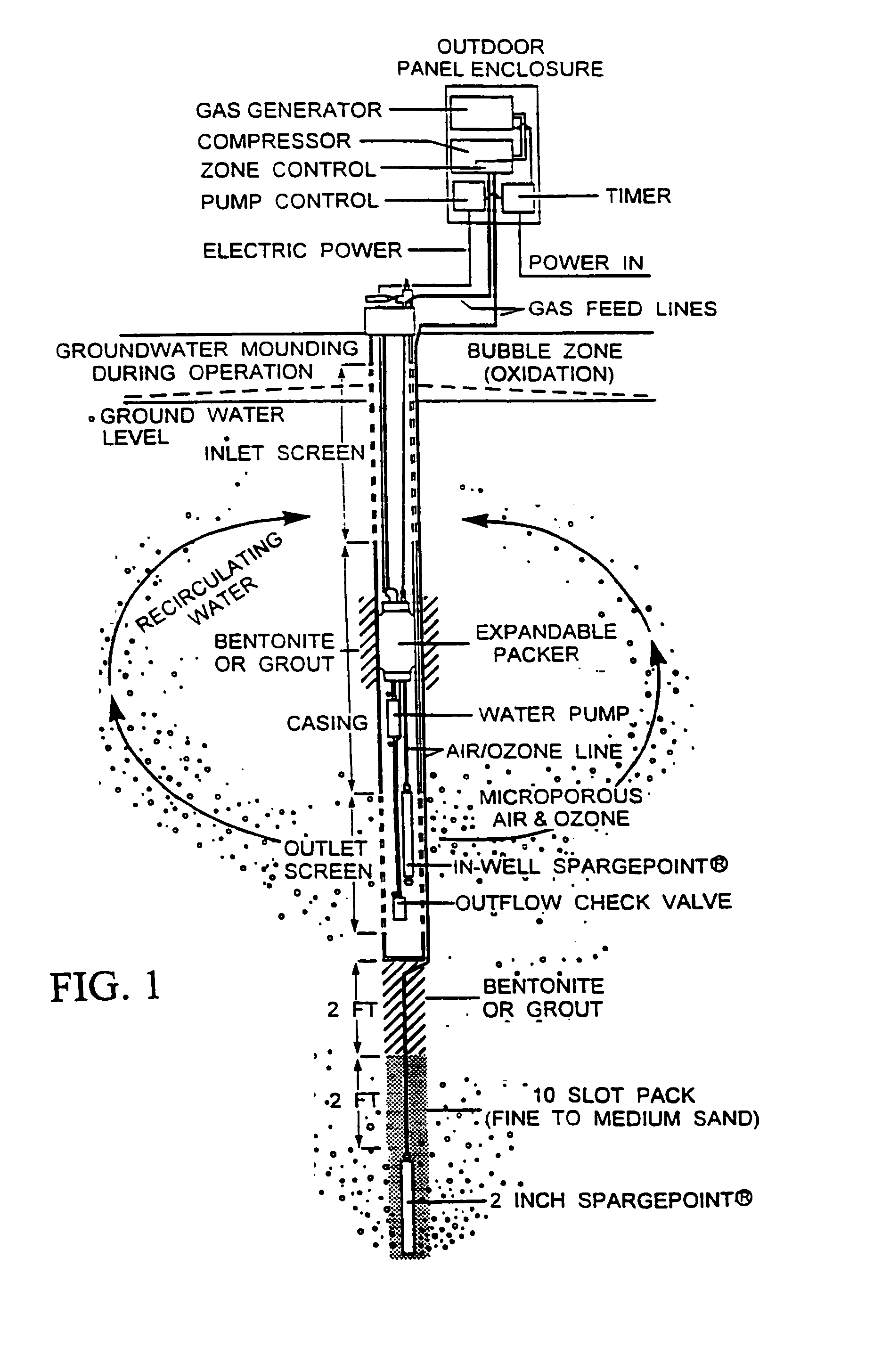
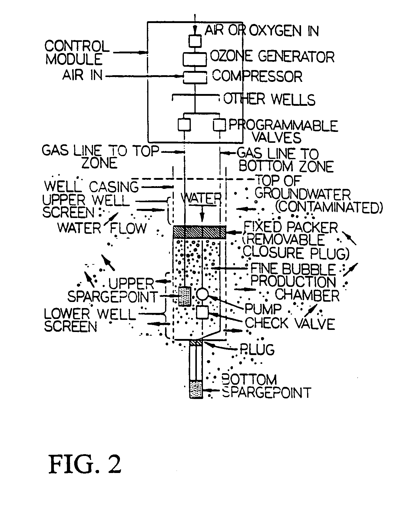
[0074]Referring to the FIGS. 1–29 there is shown a microfine sparge system employing oxidizing gas encapsulated in microbubbles generated from microporous diffusers matched to soil porosity in a wave form employing a co-reactant in the form of substrate material for use with injection wells known as the C-Sparger™ system. Said system consists of the following components: a vertical injection well, a master control unit, and at least one in-well bubble generator. Each master control unit can operate up to a total of three injection wells, simultaneously permitting treatment of an area up to 50 feet wide and 100 feet long. Actual performance characteristics of the system depend upon site conditions which are determined in advance by an evaluation test. Inasmuch as treatment takes place in-situ, vapor capture is not normally necessary. The master unit consists of the combination of a gas generator, a compressor, a pump control unit, a timer, gas feed lines, and a power source for prov...


PUM

PropertyMeasurementUnit
diameteraaaaaaaaaa
lengthaaaaaaaaaa
pressureaaaaaaaaaa

Abstract

A sparging system for in-situ groundwater remediation for removal of contamination including dissolved chlorinated hydrocarbons and dissolved hydrocarbon petroleum products including the use in injection wells of microfine bubble generators, matched to substrates of selected aquifer regions, for injection and distribution of said bubbles containing oxidizing gas through said aquifer and to selectively encapsulating gases including oxygen and ozone in duo-gas bubbles which, in the presence of co-reactant substrate material acting as a catalyst, are effective to encourage biodegradation of leachate plumes which contain biodegradable organics, or Criegee decomposition of leachate plumes containing dissolved chlorinated hydrocarbons.

Description

CROSS-REFERENCE TO RELATED APPLICATIONS[0001]This application is a continuation application of application Ser. No. 09 / 993,152 filed on Nov. 6, 2001, entitled Microporous Diffusion Apparatus (now U.S. Pat. No. 6,827,861), which was a continuation application of application Ser. No. 08 / 921,763 filed on Aug. 26, 1997 entitled Microporous Diffusion Apparatus (now U.S. Pat. No. 6,312,605), which was a continuation of application Ser. No. 08 / 756,273, filed Nov. 25, 1996, entitled Microporous Diffusion Apparatus U.S. Pat. No. 5,855,775, which was a continuation-in-part of application Ser. No. 08 / 638,017 filed on Apr. 25, 1996 entitled Groundwater and Soil Remediation with Microporous Diffusion Methods and Apparatuses, (abandoned) which was a continuation-in-part of application Ser. No. 29 / 038,499 filed on May 5, 1995 entitled Bubblersparge Unit for Ground Water Treatment (abandoned).BACKGROUND[0002]1. Field of the Invention (Technical Field)[0003]The present invention relates to sparging ...

Claims


Application Information

Patent Timeline
Patent Type & Authority Patents(United States)
IPC IPC(8): C02F1/78B09B3/00B01F3/04B09C1/00B09C1/08B09C1/10C02F3/22E21B43/00
CPCB01F3/04262B09C1/00B09C1/08B09C1/10C02F3/226E21B43/00B09C1/002B01F2003/04319B01F2003/04858B01F2003/04886B01F2215/0052Y10S210/908Y10S210/909Y02W10/10B01F23/23123B01F23/231265B01F23/2373B01F23/237613B01F2101/305
Inventor KERFOOT, WILLIAM B.
Owner KERFOOT TECH
Why Eureka
Try Eureka