Conductive resin composition

a technology of conductive resin and composition, applied in the direction of printed circuit assembling, non-conductive materials with dispersed conductive materials, greenhouse cultivation, etc., can solve the problem reduce the dependence of volume resistivity on thickness, reduce the effect of low volume resistivity

Inactive Publication Date: 2006-04-11
SHIN ETSU CHEM IND CO LTD
View PDF17 Cites 46 Cited by
  • Summary
  • Abstract
  • Description
  • Claims
  • Application Information

AI Technical Summary

Benefits of technology

[0062]Any desired additives such as antioxidants, heat stabilizers, inorganic fillers (e.g., silica, alumina), pigments, and dyes may be added to the conductive resin composition of the invention insofar as the effectiveness of the invention is not affected.
[0063]The conductive layer which is formed of the inventive conductive resin composition is characterized by the reduced dependency of volume resistivity on thickness and a low volume resistivity over a wide range of thickness. Since conductivity is imparted without significantly reducing the substrate adhesion and low modulus characteristic of the binder resin, the conductive layer, when used in the bonding of a semiconductor chip to a lead frame, is effective for restraining the semiconductor chip from warpage and cracking due to thermal stresses, ensuring fabrication of a semiconductor device with high reliability. The inventive conductive resin composition will also find use in formation of conductive bumps, joint of electrical contacts, and formation of wiring patterns, and in a variety of applications where conductivity and processability are required.EXAMPLE
[0064]Examples of the invention are given below by way of illustration and not by way of limitation. It is noted that the viscosity is a measurement at 23° C.
[0065]The volume resistivity was measured by the following procedure in accordance with the Society of Rubber Industry Japan, Standard SRIS 2301-1969.Measurement of Volume Resistivity
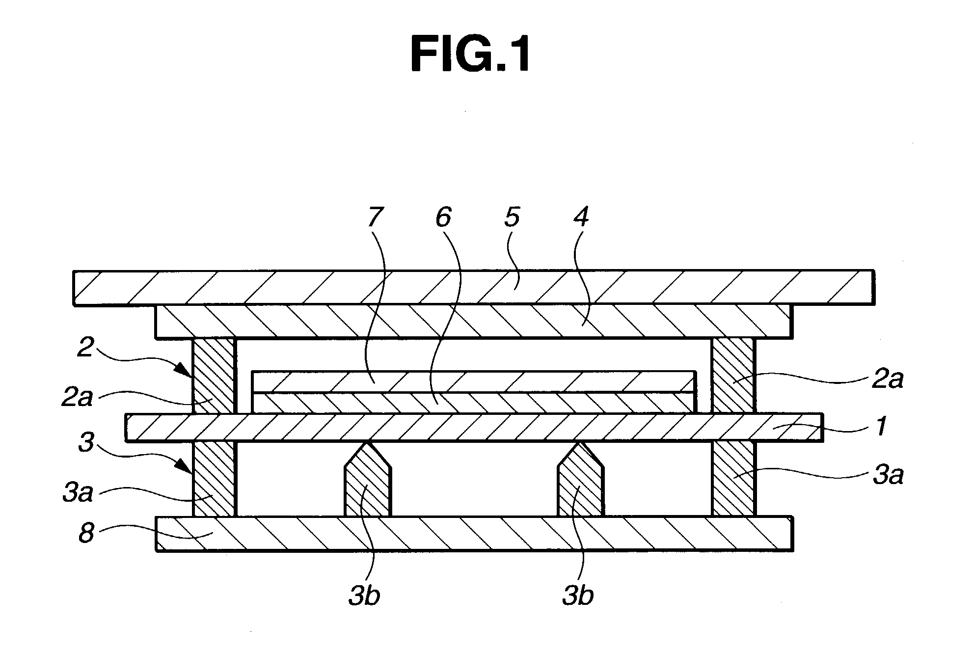
[0066]Referring to FIG. 1, a test piece 1 of 150 mm long, 20 mm wide and 0.01 to 1.0 mm thick is sandwiched between upper and lower electrodes 2 and 3. The upper electrode 2 includes a pair of current terminals 2a and 2a of 30 mm long, 15 mm wide and 5 mm thick which are attached to an insulator 4 of polyethylene. A weight 5 rests on the insulator 4 so that a weight of 5 kg is applied to the current terminals 2a and 2a. The lower electrode 3 includes a pair of current terminals 3a and 3a of 30 mm long, 15 mm wide and 5 mm thick and a pair of knife shaped voltage terminals 3b and 3b of 30 mm long and 5 mm wide. The pair of current terminals 3a and 3a of the lower electrode 3 are opposed to the pair of current terminals 2a and 2a of the upper electrode 2. A weight 7 of 0.5 kg rests on an insulating plate 6 on the test piece 1. The lower electrode 3 is set on an insulating plate 8. In this condition, the upper and lower electrodes 2 and 3 are electrically connected for measuring the volume resistivity of the test piece.
[0067]Complex elastic modulus was measured at 25° C. and 30 Hz by a dynamic viscoelasticity spectrometer (Yoshimizu Corp.).

Problems solved by technology

It has been found that compounding a thermosetting or thermoplastic resin binder with specific amounts of a conductive filler and a particulate organic resin or rubber results in a low volume resistivity despite the reduced content of the conductive filler.

Method used


Image

  • Conductive resin composition
  • Conductive resin composition
  • Conductive resin composition

Examples


synthesis example 1

[0074]A flask equipped with a stirrer, thermometer and nitrogen inlet was charged with 9.66 g (0.03 mol) of BTDA as a tetracarboxylic dianhydride component and 30 g of N-methyl-2-pyrrolidone. To the flask, 17.0 g of a N-methyl-2-pyrrolidone solution containing 6.00 g (0.03 mol) of DPE as a diamine component was added dropwise at a controlled rate so that the temperature of the reaction system might not exceed 50° C. After the completion of dropwise addition, the reaction solution was stirred for 12 hours at room temperature for driving the reaction to completion, yielding a yellowish brown clear solution of polyamic acid. The solution had a viscosity of 29 Pa·s and a resin solids content of 25.1%. This is designated polyamic acid solution No. 1.

synthesis example 2

[0075]In a reactor as used in Synthesis Example 1, 29.42 g (0.10 mol) of BPDA, 7.46 g (0.03 mol) of APM and 28.73 g (0.07 mol) of BAPP were reacted in 196.8 g of cyclohexanone at room temperature for 12 hours, yielding a solution of polyamic acid. To the polyamic acid solution was added 30 g of toluene. A Dimroth condenser with a Dean-Stark trap was attached to the reactor where reaction was conducted at 180° C. for 8 hours, synthesizing a solution of polyimide resin. The solution had a viscosity of 66 Pa·s and a resin solids content of 25.3%. This is designated polyimide solution No. 1.

synthesis example 3

[0076]A glass beaker having a volume of 1 liter was charged with 500 g of methylvinylsiloxane of the formula (i) having a viscosity of 600 cS and 20 g of methylhydrogenpolysiloxane of the formula (ii) having a viscosity of 30 cS.

[0077]

The contents were agitated and mixed by operating a homo-mixer at 2,000 rpm. With 1 g of polyoxyethylene (9 moles addition) octylphenyl ether and 150 g of water added, agitation was continued at 6,000 rpm until phase inversion occurred, with thickening observed. While the solution in this state was sequentially agitated at 2,000 rpm, 329 g of water was added, yielding an O / W type emulsion. The emulsion was then transferred to a glass flask equipped with an agitator having an anchor-shaped impeller. While agitating at room temperature, a mixture of 1 g of a toluene solution of a chloroplatinic acid-olefin complex (platinum content 0.05%) and 1 g of polyoxyethylene (9 moles added) octylphenyl ether was added to the emulsion whereupon reaction was effecte...


PUM

PropertyMeasurementUnit
elastic modulusaaaaaaaaaa
volume resistivityaaaaaaaaaa
particle sizeaaaaaaaaaa

Abstract

A conductive resin composition primarily comprising (A) 100 parts by weight of a thermosetting or thermoplastic resin, (B) 5–2,000 parts by weight of a conductive filler, and (C) 0.1–300 parts by weight of organic resin or rubber particulates has a low volume resistivity and stability thereof, and is effectively adherent. When applied to semiconductor packages, the composition can prevent the semiconductor chips from warpage or cracking due to thermal stresses in the semiconductor packages, ensuring the fabrication of semiconductor devices with high reliability.

Description

FIELD OF THE INVENTION[0001]This invention relates to conductive resin compositions having a low volume resistivity, stability thereof, a low modulus and good adherence, and useful as conductive adhesives, electrical contacts and conductive lines on semiconductor chips and substrates for semiconductor devices. The term “conductive” used herein refers to electrical conduction throughout the specification.BACKGROUND OF THE INVENTION[0002]In the manufacture of semiconductor devices involving the bonding of semiconductor chips to lead frames, a technique of using gold-plated lead frames or pieces of gold tape to form Au—Si eutectic was effective in the past because of its high reliability, but has been replaced by the use of conductive pastes for economical and other reasons. Most conductive pastes used contain metal powder such as silver in organic resins as a binder. In conjunction with the recent tendency of increasing the size of semiconductor chips or elevating the solder reflow te...

Claims


Application Information

Patent Timeline
Patent Type & Authority Patents(United States)
IPC IPC(8): C08K5/54C08L63/00C08L77/00C08L79/00H01B1/24C08K3/08C08L101/00C08K9/02H01B1/00H01B1/22H05K3/32
CPCH05K3/321H01B1/22C08L101/00C08L83/14C08L83/04C08G77/045C08G77/12H05K2201/0212C08G77/14C08G77/20C08G77/24C08G77/26C08G77/28C08G77/70C08L2666/02C08L83/00
Inventor AKIBA, HIDEKIYOSHINO, MASACHIKAICHIROKU, NOBUHIROSHIOBARA, TOSHIO
Owner SHIN ETSU CHEM IND CO LTD
Why Eureka
Try Eureka