
Method and apparatus for forming optical materials and devices

a technology of optical materials and forming methods, applied in the field of fabrication of optical materials, can solve the problems of complicated fabrication techniques, complicated and complicated, and is especially bothersome, and achieve the effects of simplifying the fabrication of optical components, reducing solubility, and improving optical properties

Inactive Publication Date: 2006-04-11
EBEAM & LIGHT
View PDF14 Cites 12 Cited by
  • Summary
  • Abstract
  • Description
  • Claims
  • Application Information

AI Technical Summary

Benefits of technology

[0009]The invention provides a process for forming optical components and new optical materials utilizing electron beam irradiation. The process comprises selectively irradiating optical materials to alter their index of refraction three dimensionally. With the inventive process, new optical materials can be created by altering the bond structure within the material such that enhanced optical properties are achieved over the native un-irradiated material. The invention also provides a process in which optical components can be fabricated without requiring a planar / multiple layer process, thereby simplifying the fabrication of these optical components. The inventive process uses a controlled electron beam to alter the properties of optical materials. For example, by using the radiation of a controlled electron beam, controlled changes in the index of refraction gradient of optical materials can be obtained. Further, radiation of the electron beam can be used to create new optical materials from materials not previously believed to be suitable for optical applications. This is based not only on the refractive index change created in the material, but also upon the change in other material properties such as elimination of melt and reduced solubility in normal solvents. In these cases, the electron beam modifies and creates a new networks structure within the material, which enhances its optical properties and allows for the formation of useful physical properties necessary for the fabrication of useful devices (i.e., resulting in wholly new optical materials). It has also been determined that the inventive process can be used to produce a spatially graded index of refraction within a material to enhance the performance of an optical waveguide which can lead to a number of novel structures. In addition, it is possible to create differing zones of optical properties within a homogenous material by selectively exposing the material to radiation from a controlled voltage electron beam system. By controlling the incident energy of the electron beam, one can alter the optical properties as a function of depth to create a layered structure within a previously homogenous material layer.

Problems solved by technology

The multiple layers of different materials create problems in fabrication as edge breakage and differential polishing rates between the glue and core / cladding materials must be taken into account as well as controlling appropriate glue thickness.
These fabrication techniques are further complicated if optical adhesives are used which then must have the appropriate optical index for the device to work properly.
For example, when distinctly different materials are used such as grating formation in waveguides fabricated using these techniques, complications arise due to the different exposure response of the two materials.
This is especially bothersome in the case of narrow line width gratings.
In the current state of the art, optical materials that can be processed which exhibit high transmission, low birefringence, and selected optical indices are very expensive and the range of indices is very limited, especially between compatible materials.

Method used


Image

  • Method and apparatus for forming optical materials and devices
  • Method and apparatus for forming optical materials and devices
  • Method and apparatus for forming optical materials and devices

Examples


Embodiment Construction

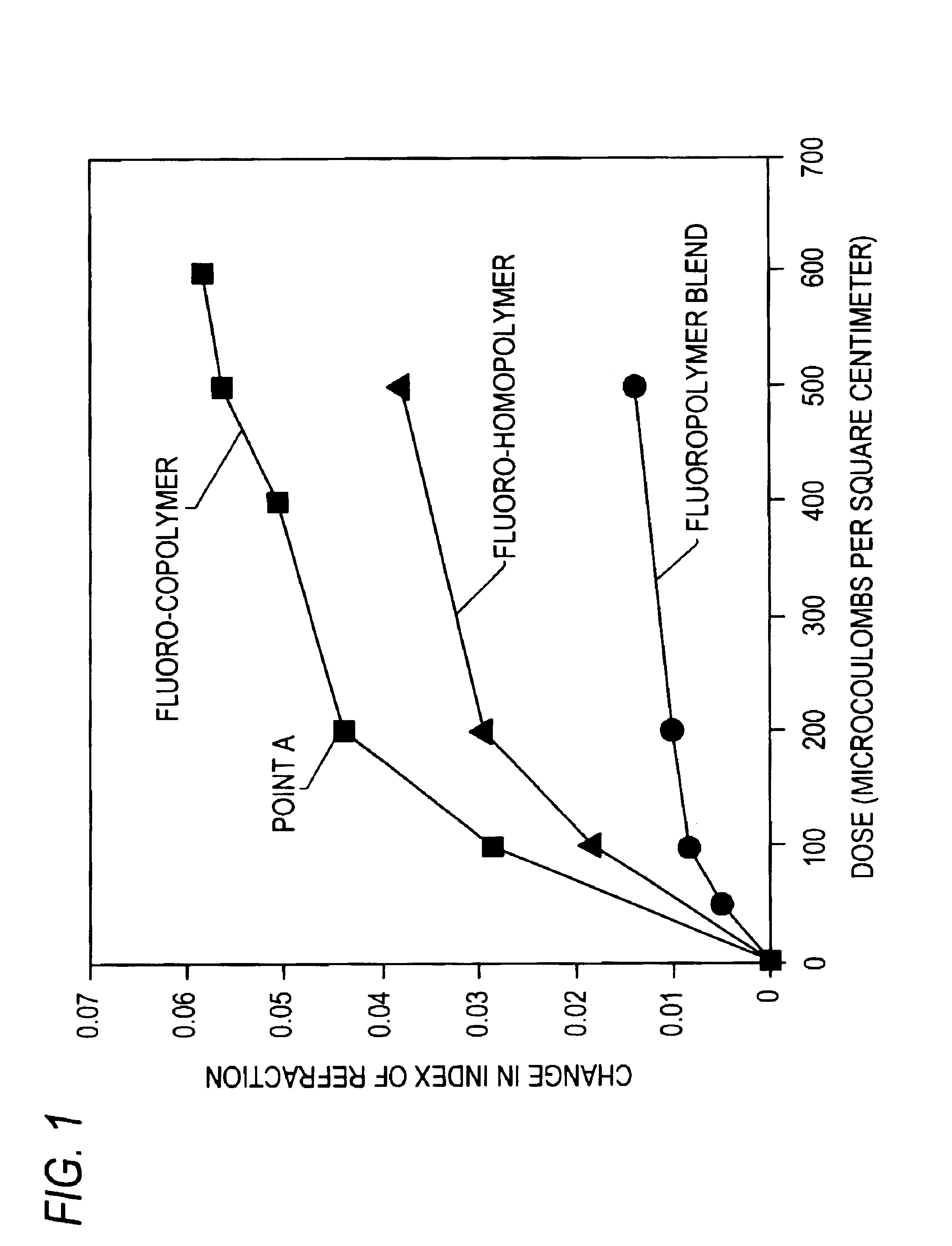
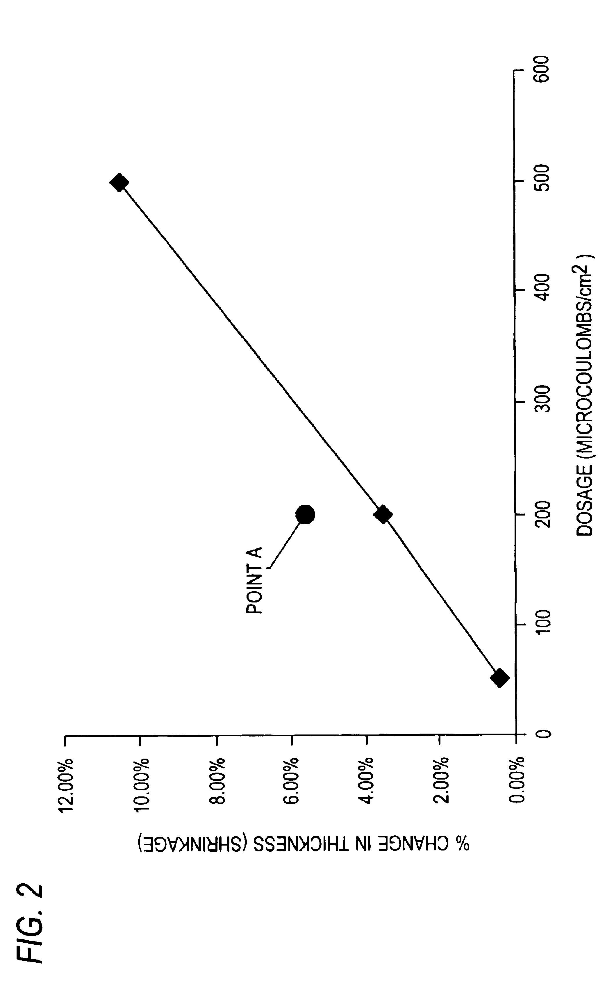
[0032]The exposure of selected optical materials to electron beam irradiation can convert the existing material into a new state which exhibits more desirable optical and mechanical properties not present in the un-irradiated material. An example of this can be seen in FIGS. 1 and 2 which shows a plot of surface refractive index as a function of electron dosage and overall thickness respectively in a uniformly irradiated sample as a function of electron dosage for several amorphous fluoropolymers. The new optical material was created only by exposure to the electron beam. The introduction of extra bonds within, in this case, a high polymer results not only in large index change but also results in insolubility in a solvent of the original (irradiated) materials. This conversion can be done selectively in 3 dimensions in either a continuous or periodic manner in normally non-reactive material systems including oil, waxes, monomers, oligomers, and high polymers such that a number of o...


PUM


Abstract

The invention provides a process for forming optical components and new optical materials utilizing electron beam irradiation. The process comprises selectively irradiating optical materials to alter their index of refraction gradient three dimensionally. With the inventive process, new optical materials can be created that have enhanced optical properties over the un-irradiated material. The invention also provides a process in which optical components can be fabricated without requiring a planar / multiple layer process, thereby simplifying the fabrication of these optical components. The inventive process uses a controlled electron beam to alter the properties of optical materials. By using the radiation of a controlled electron beam, controlled changes in the index of refraction gradient of optical materials can be obtained. Further, radiation of the electron beam can be used to create new optical materials from materials not previously believed to be suitable for optical applications. This is based not only on the refractive index change created in the material, but also upon the change in other material properties such as elimination of melt and reduced solubility in normal solvents. In these cases, the electron beam modifies and creates a new networks structure within the material, which enhances its optical properties and allows for the formation of useful physical properties necessary for the fabrication of useful devices (i.e., resulting in wholly new optical materials). It is also disclosed that the inventive process can be used to produce a spatially graded index of refraction within a material to enhance the performance of an optical waveguide which can lead to a number of novel structures.

Description

[0001]This application claims the benefit of Provisional Application No. 60 / 302,152, filed Jun. 28, 2001.BACKGROUND OF THE INVENTION[0002]1. Field of the Invention[0003]The present invention relates generally to the fabrication of optical materials used in optical communication and integrated optical circuits using electron beam radiation and more specifically to a method for fabricating optical devices by inducing changes in the index of refraction in optical materials utilizing electron beam radiation.[0004]2. Description of the Prior Art[0005]Optical materials such as polymers and spin-on-glasses have found widespread use in optical communication and integrated optics applications. Typically, these optical materials are utilized to form waveguides and carry optical signals along a designated path. These optical waveguides are typically formed by utilizing materials of different refractive index. The inner waveguide material typically exhibits high optical transmission and has a h...

Claims


Application Information

Patent Timeline
IPC IPC(8): H01J31/30G03F1/16G03F7/20G02B6/12G02B6/13H01J37/317
CPCB82Y10/00B82Y40/00H01J37/3175G02B6/13G02B2006/12107G02B2006/12195
Inventor LIVESAY, WILLIAM R.ZIMMERMAN, SCOTT M.
Owner EBEAM & LIGHT
Learn More