Universal method and apparatus for conversion of volatile compounds

a technology of volatile compounds and conversion methods, applied in the field of universal methods and conversion methods of volatile compounds, can solve the problems of increasing the restrictions on the discharge of such contaminants, high energy and power penalties, and many methods used are prohibitively expensive, so as to increase the ultimate process capture efficiency, reduce the concentration of volatile contaminants, and reduce the effect of volatility

Inactive Publication Date: 2006-04-18
MCGINNESS MICHAEL P
View PDF8 Cites 43 Cited by
  • Summary
  • Abstract
  • Description
  • Claims
  • Application Information

AI Technical Summary

Benefits of technology

[0032]A method or process of treating a contaminated fluid having at least one contaminant having a property selected from the group consisting of being volatile, hazardous, tacky and a combination thereof is provided. The method comprises contacting the contaminated fluid with an effective amount of an agent selected from oxidizing agents, free radical producing agents and a combination thereof for an effective amount of time to convert a substantial amount of the at least one contaminant to at least one corresponding modified contaminant having a property selected from the group consisting of being non-volatile, less volatile than the contaminant, non-hazardous, less hazardous than the contaminant, non-tacky and a combination thereof, and generating a treated fluid having a level of the at least one contaminant and of the at least one corresponding modified contaminant to allow the treated fluid to at least meet requirements for release, reuse or further treatment.
[0037]Further, in a main process that utilizes a contacting liquid and generates at least one main liquid containing a contaminant, the process according to the present invention, for example, as shown in FIG. 1, may be used to treat such main liquid as a contaminated fluid. When there is a plurality of main liquid streams, the plurality of main liquid streams are combined to form the contaminated fluid. Additionally, at least a portion of the treated fluid may be recycled to the main process as part of or as the contacting liquid. In another embodiment, only a minor portion of the at least one main liquid is provided as a slip-stream for treatment. This allows for a more continuous operation of the main process.
[0040]One preferred embodiment includes treatment of water-wash-paint-booth-wash water. By introducing the water of the booth into the reactor of the invention, the contaminants are converted to intermediate products that enhance the scrubber solution used in the paint booth. The reactor can be integral with the stripper or can be a separate vessel. The regenerated solution can then be returned to the paint booth, fed to a bioreactor, discharged to a local POTW (Publicly Owned Treatment Works) for further treatment, a combination of these items or used in other ways. To avoid oversaturation of the wash water with intermediate products created by the oxygenation reaction, a slip-stream can be removed from the main wash water and treated such that the intermediate products are completely oxidized or the slip-stream can be removed to another location, such as bioreaction, for example, in a bioreactor that converts the organic components in the slip-stream into methane biogas in an anaerobic bioconversion or into fertilizer in an aerobic bioconversion. When the slip-stream is removed, makeup water solution is added to the wash water. Makeup water solution for the water wash booth can be bioreactor treated and filtered water that is subsequently returned to the water wash booth, fresh water feed, or used rinse water from a cleaning process rinse. A particularly desirable embodiment includes treating a slip-stream of the wash water solution in the stripper / reactor rather than the entire volume simultaneously. In this fashion, the stripper / reactor vessel size is substantially reduced along with minimizing capital and operating costs. The stripper / reactor can then function during times when the paint booth is not in use, in addition or in place of those times when the booth is in use. The ozone generator capacity requirements are also minimized, for example, at least by a factor of 10, in this fashion further reducing costs of regeneration.
[0042]The reactor of the invention is also useful in treating cleaning and phosphate baths. Cleaning baths used in many industries, particularly where metal is cleaned prior to painting, accumulate the contaminants discussed above, oils, greases, solvents, metal fines, ionic metals and other soils. As described above, these cleaning solutions can be regenerated by oxygenation of the contaminants. Oxygenation creates a cleaning solution with additional surface active components thus increasing the specific emulsifying and soil carrying capacity of the cleaning solution. The reaction of the invention can take place in a separate vessel that receives all or part of the cleaning bath to be regenerated, or the vessel used for the bath itself can be used as the reactor, or as one of the reactors. Furthermore, this invention includes the addition of the oxygenation reagents (such as ozone) as phosphate coating accelerators for the pre-paint metal finishing process in the phosphate coating bath. Furthermore, this invention includes the addition of oxygenation reagents (such as ozone) that act as phosphate coating accelerator compound regenerators (ClO3 regeneration, for example), and producers of secondary phosphate coating accelerator compounds such as peroxides and hydroxide free radicals. Since many of these phosphate coating processes are also parts cleaners (they contain wetting and cleaning agents to disperse any remaining soils in order to insure that a uniform phosphate coating is formed), the additional benefit of increasing the soil carrying capacity of the cleaner and therefore extending the useful life of the cleaner—phosphate solution (by converting certain unsaturated and / or aromatic contaminants into emulsifying and cleaning agents) is achieved, while extending and regenerating the phosphate coating solution's original phosphate coating accelerator compound. Both the phosphate coating accelerator and cleaner properties must be regenerated to be able to reuse the phosphate coating solution. Typically, these phosphate coating parts cleaner baths are frequently (sometimes weekly) dumped and replaced with new product.
[0045]Off-gasses, such as those produced by the burning of fossil fuel, emissions from bakeries and restaurants, and emissions from paint ovens, can be treated in another embodiment of the invention or captured in a scrubber first and then treated in the stripper / reactor as previously described. For off-gases that are already hot, one of the preferred embodiments would include a counter-current flow scrubber where the hot exhaust gases are progressively cooled and the scrubber liquid is progressively heated as they both flow through the scrubber in a counter-current flow. Some volatile compounds would be condensed and their volatility reduced due to the temperature profile of the scrubber. The hot gas feed would tend to re-volatize the condensed volatiles leading to an increased concentration of volatile contaminants in the scrubber. By feeding the oxygenation reagent into the scrubber at a point between the gas and liquid feeds where the accumulating volatile contaminant is still volatile, it can be reacted with the oxygenation reagent in the gas phase. This results in a scrubber / reactor combination embodiment as distinguished from the previously described stripper / reactor. Cleaned off-gas is exhausted from the scrubber / reactor to further treatment, if needed, re-used or vented to the atmosphere. Heat recovery is possible from the scrubber liquid. After the scrubber liquid is cooled, the scrubber liquid can be re-used in the scrubber / reactor. Scrubber / reactor and stripper / reactor combinations are also possible and can be combined to increase ultimate process capture efficiency. In such a case, the scrubber liquid and stripper liquid would circulate in a loop with the off-gas contaminated exhaust feed to the scrubber being the source of volatile contaminants being captured and controlled. The result of combining both embodiments is a gas stream meeting regulatory requirements and a liquid stream that has been regenerated.
[0046]An alternate embodiment would include the treatment of sticky tacky fluids, flowable sludges and wastes (perhaps with prior dilution to form a pumpable solution) with poor filtration properties. By treating these materials first with the stripper / reactor process, and thereby detackifying the solution, filtration of the resultant detackified solution is enabled. In some cases, a partial polymerization and aggregation of molecules will occur as well as improving the filterability of the solution This is in addition to other possible benefits described above. Filtration of sticky tacky paint contaminated paint booth wash water and similar sticky tacky used contaminated scrubber liquids, and other similar process or waste liquids and sludges is not possible or economical unless they are first some how detackified. Water wash paint booths have in the past been detackified using chemical additives such as clays, organic detackifiers, polymers and flocculates at substantial cost to the customer.

Problems solved by technology

Regulatory control in the United States and other countries has led to constantly increasing restrictions on discharge of such contaminants.
While various separation and destruction methods have been utilized to remove contaminants from those waste products requiring disposal, many of the methods utilized are prohibitively expensive, especially for small facilities with limited resources.
Low concentration high volume flows carry large energy and power penalties when treated with conventional technologies, and contribute to green house gas problems.
Many small emission sources remain uncontrolled due to the prohibitive cost of installing and operating conventional systems.
In other industries, the contaminants are absorbed into a liquid solvent making the solvent unfit for further use.
Such occurrences lead to the need for remediation.
Hydrocarbon and petrochemical industries are affected by these restrictions.
Industries that burn fossil fuels, such as for power generation, are also affected by these emission limits.
When multiple solvents are combined prior to being regenerated, close relative volatilities and azeotropes can make equilibrium separation particularly difficult.
While solvent can be recovered by this method, some solvent is typically lost to the contaminant by-product.
Filter media with contaminants then face the same disposal challenge since the contaminants are trapped within the media.
Destruction techniques typically involve large additional energy inputs and substantial space requirements.
This combination is often economically inefficient for significant volumes of throughput and wastes limited hydrocarbon resources.
Particulate matter tends to negatively affect some incineration processes as well as release particulate matter that contributes to ground level ozone (smog) formation.
However, when only low concentrations of the contaminant are available, large amounts of energy must be added to the effluent stream to reach the required temperature to destroy the contaminants.
In addition to creating thermal pollution and green house gases, it makes thermal oxidation inefficient and cost prohibitive.
Disposal of liquid and / or solid wastes containing these contaminants is also costly.
Some of the difficulties involved with this technology include the expense and difficulties of maintaining and regenerating the silica gel bed, particularly as the bed tends to foul when particulate matter is introduced in the stream to be treated.
Both of the above methods require substantial amounts of ozone to achieve their goals.
Ozone is undesirable as an off-gas.
Liquid scrubbers also frequently require expensive additives, such as metal chelates, defoamers, pH additives, reactive agents or other specialty chemicals.
Scrubbing liquids are frequently selective to specific contaminants making them impractical for systems containing multiple contaminants.
Many industries have similar problems with treatment or disposal of contaminants from waste products.
The-paint and coating industry is particularly plagued with problems due to the nature of the paints and coatings they use and produce.
Various organic and synthetic oil systems are also used in liquid scrubbers but have not found favor in the paint booth scrubber application due to their cost and various recycling problems.
Peculiar to paint spray booths (as opposed to many other scrubber applications) is the issue that the paint hardens or becomes tacky and sticky as solvent evaporates from the previously captured paint particles.
Paint collected in air filters or in a wash section that is subjected to heat or drying becomes tacky.
This causes, a problem in every aspect of paint booth operation, from the cleaning of equipment, walls and tanks to the further processing of removed sludge and solids.
These chemical additions are expensive in that they are costly to buy, require bath titrations and calculations to determine the correct amount and frequency of addition needed to maintain the booth, and increase the final disposal volume and cost by up to 400%.
Since most industrial operations, including manufacturers, do some painting, the problems associated with painting operations are widespread.
The paint industry also produces paint sludge and substantial quantities of unused paint that must be discarded.
Currently, sludge from existing water wash paint booths, and sludges from other industries that contain hazardous organic ingredients, solvents or metals, require very special and costly treatment.
Separation of hazardous waste metals, water and organics from various waste streams that vary substantially from batch to batch make separation process scaleups nearly impossible to consider.

Method used


Image

  • Universal method and apparatus for conversion of volatile compounds
  • Universal method and apparatus for conversion of volatile compounds
  • Universal method and apparatus for conversion of volatile compounds

Examples


Embodiment Construction

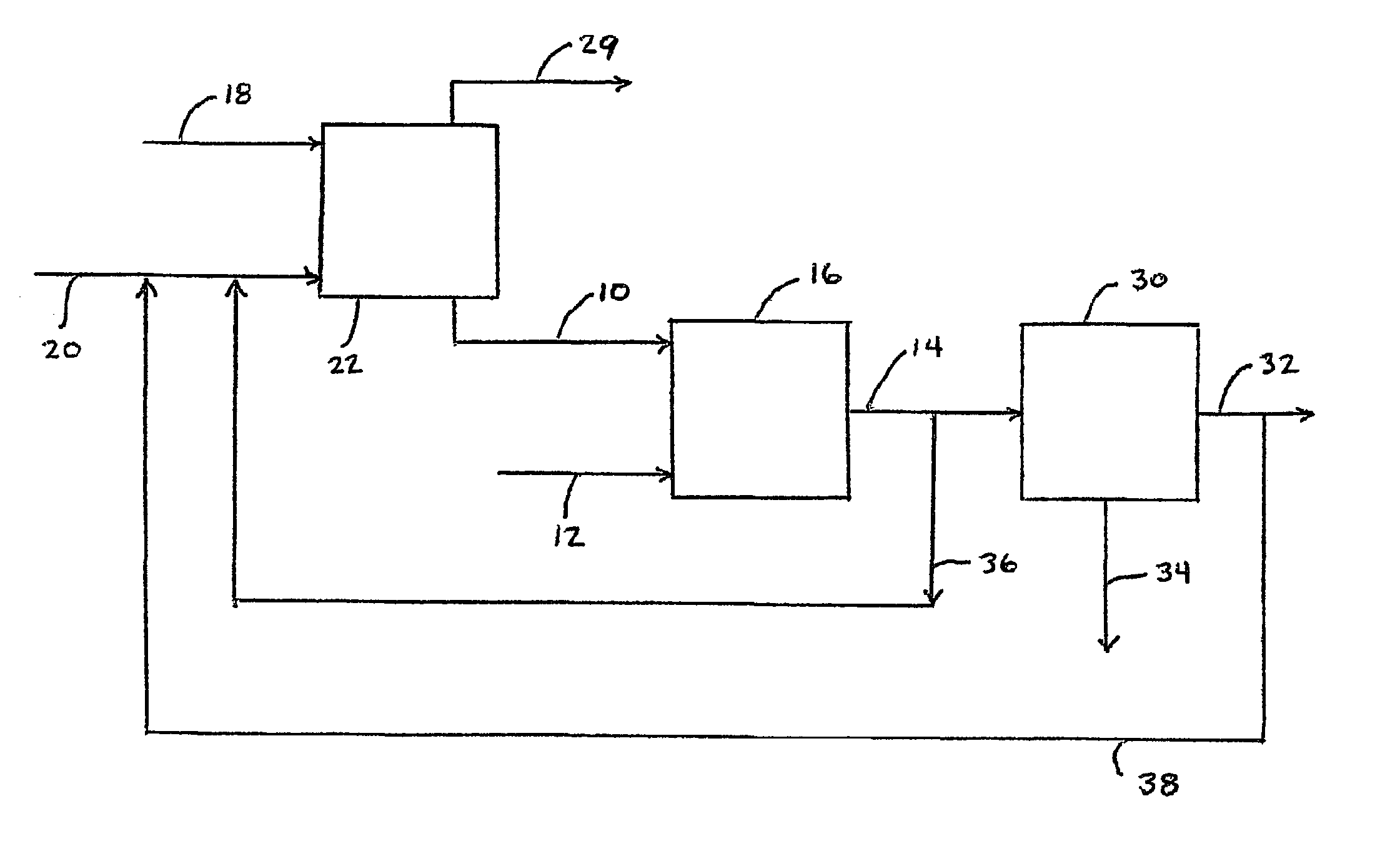
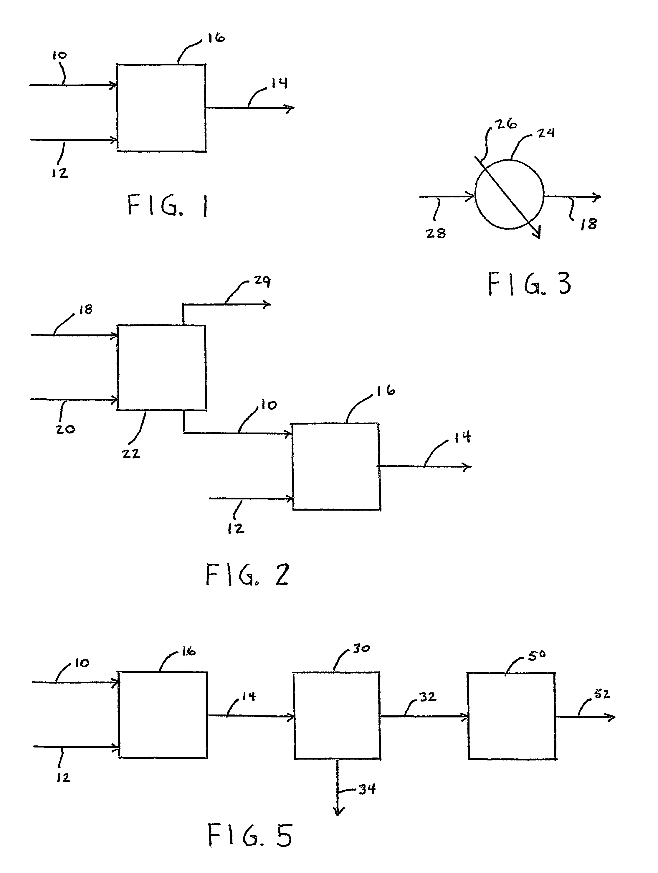
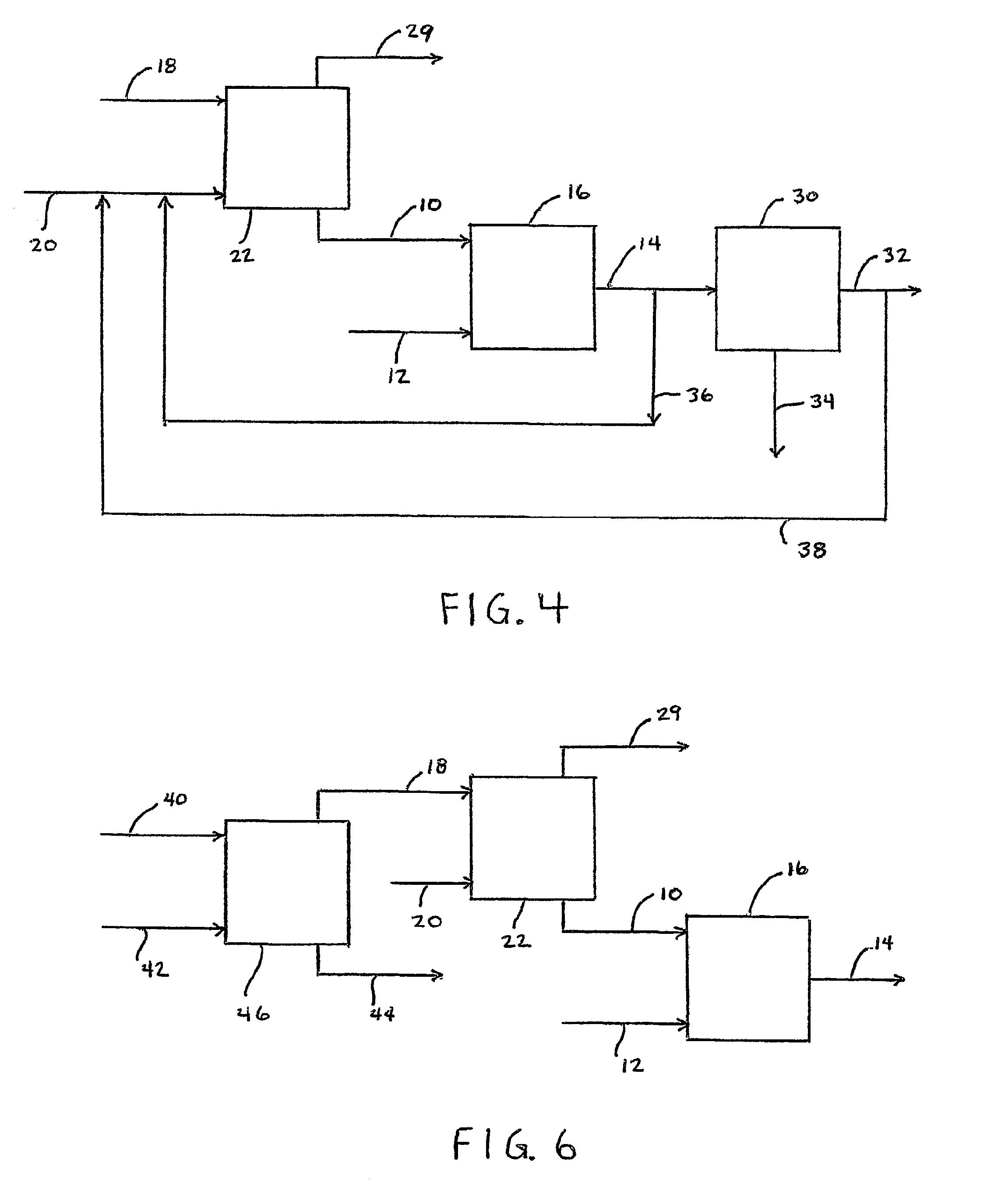
[0060]The current invention includes a process and apparatus for reacting the contaminants with an oxygenation source to convert the contaminants primarily to intermediate products with desirable characteristics. By contacting volatile organic contaminants with the limited oxygenation source, such molecules are converted into compounds that preferably are themselves much less volatile or non-volatile. This limited reaction produces a range of products, depending on the contaminants. Ketones, aldehydes, alcohols, polyols and compounds containing carboxylic acid and / or carbonyl functional group(s) can result. By controlling and limiting the oxygenation reaction to create the intermediate products such as the salts of carboxylic acids, di-acids, polyols and amphoteric compounds such as diacid polyols and the like, the contaminants are modified into components that act as volatile compound absorbents that can emulsify additional volatile components, that would not be otherwise captured,...


PUM

PropertyMeasurementUnit
timeaaaaaaaaaa
solubilityaaaaaaaaaa
volatileaaaaaaaaaa

Abstract

A method or process of treating a contaminated fluid (10) having at least one contaminant having a property selected from the group consisting of being volatile, hazardous, tacky and a combination thereof is provided. The method comprises contacting the contaminated fluid with an effective amount of an agent (12) selected from oxidizing agents, free radical producing agents and a combination thereof for an effective amount of time to convert a substantial amount of the at least one contaminant to at least one corresponding modified contaminant having a property selected from the group consisting of being non-volatile, less volatile than the converted contaminant non-hazardous, less hazardous than the converted contaminant, non-tacky and a combination thereof; and generating a treated fluid (14) having a level of the at least one contaminant and of the at least one corresponding modified contaminant to allow the treated fluid to at least meet requirements for release, reuse or further treatment.

Description

[0001]This application claims the benefit of Provisional Application No. 60 / 194,445, filed Apr. 4, 2000.BACKGROUND OF THE INVENTION[0002]1. Field of the Invention[0003]The present invention relates to a method and apparatus to control and limit the emission and discharge of volatile and malodorous contaminants, such as those identified as VCs, VOCs, VICs, NOx, SOx, MCs, HAPs and other regulated contaminants,[0004]2. Description of Prior Art[0005]Numerous compounds used in various industries are recognized as environmental health hazards and pollutants. Regulatory control in the United States and other countries has led to constantly increasing restrictions on discharge of such contaminants. While various separation and destruction methods have been utilized to remove contaminants from those waste products requiring disposal, many of the methods utilized are prohibitively expensive, especially for small facilities with limited resources. Low concentration high volume flows carry larg...

Claims


Application Information

Patent Timeline
Patent Type & Authority Patents(United States)
IPC IPC(8): C02F1/00B01D47/00C02F1/20C02F1/24C02F1/32C02F1/72C02F1/78C02F3/00
CPCB01D47/00C02F1/72C02F1/722C02F1/78Y10S210/93C02F1/20C02F1/24C02F1/32C02F3/00C02F2101/105C02F2101/20C02F2101/322C02F2103/14C02F2103/18C02F2103/44Y10S210/908Y10S210/906C02F1/001
Inventor MCGINNESS, MICHAEL P.
Owner MCGINNESS MICHAEL P
Why Eureka
Try Eureka