Photon emitter and data transmission device

a technology of photon emitter and data transmission device, which is applied in the direction of solid-state devices, lasers, semiconductor lasers, etc., can solve the problems that the photon emitter in p. michler et al. is not suitable for mass application, and achieves the effect of further increasing the efficiency of the photon emitter

Inactive Publication Date: 2006-04-18
INFINEON TECH AG
View PDF8 Cites 12 Cited by
  • Summary
  • Abstract
  • Description
  • Claims
  • Application Information

AI Technical Summary

Benefits of technology

[0038]In accordance with a further refinement of the invention, a tunnel barrier layer is provided between the third reflector layer and the quantum-dot layer and / or between the quantum-dot layer and the fourth reflector layer, in order to prevent tunnelling of the charge carriers from the quantum dots into the confinement layers.
[0039]The efficiency of the photon emitter is further increased by means of this refinement of the invention.
[0040]In accordance with a further refinement of the invention, at least one optical wing mirror is fitted on at least one side wall of the second resonator, preferably around the entire circumference of the second resonator. The entire circumference of the second resonator is preferably provided with optical wing mirrors in order further to increase the efficiency of the photon emitter.

Problems solved by technology

For this reason, the photon emitters in J. M. Gerard and B. Gayral, or P. Michler et al. are not suitable for application on a massive scale.

Method used


Image

  • Photon emitter and data transmission device
  • Photon emitter and data transmission device
  • Photon emitter and data transmission device

Examples


Embodiment Construction

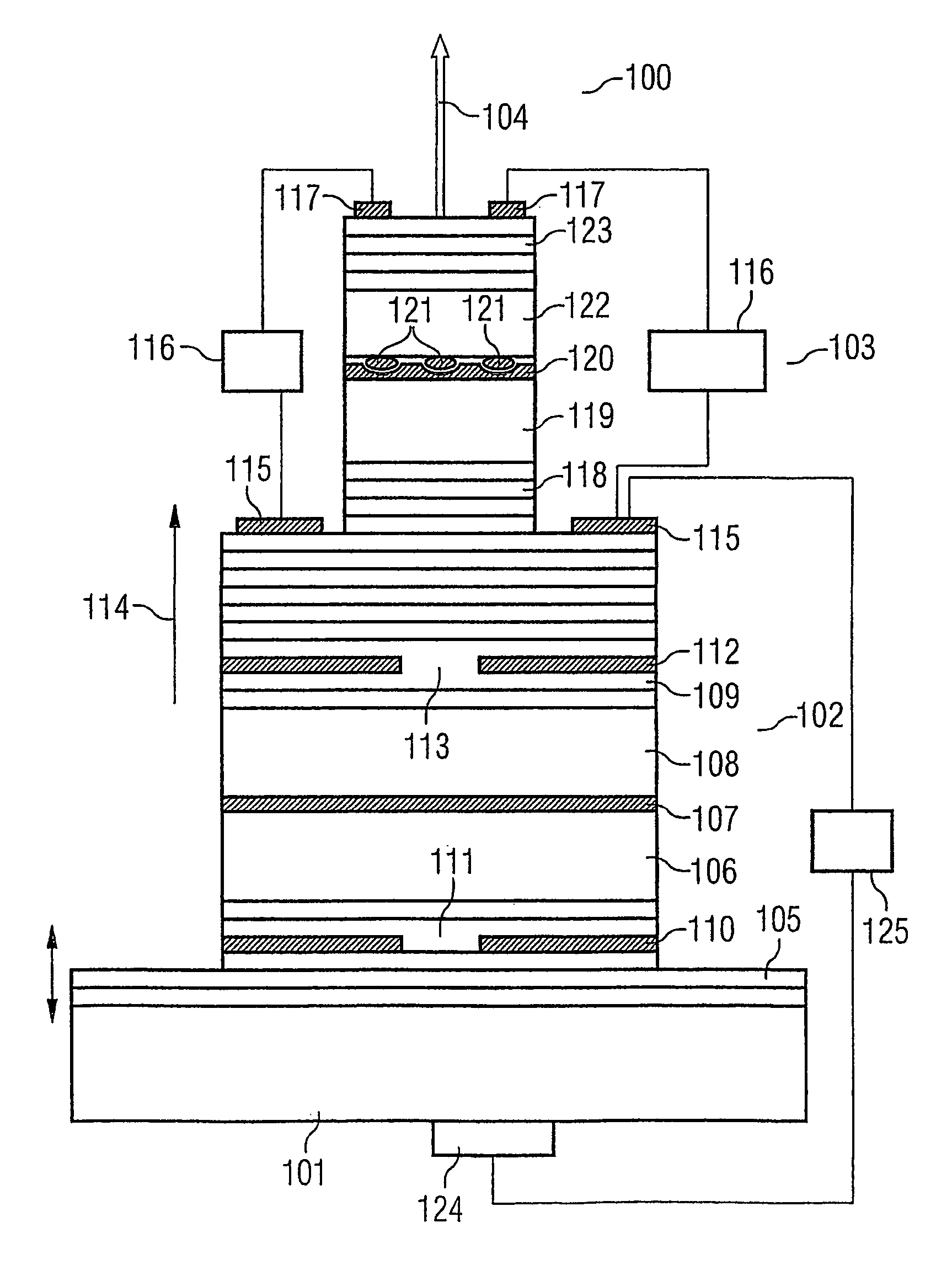
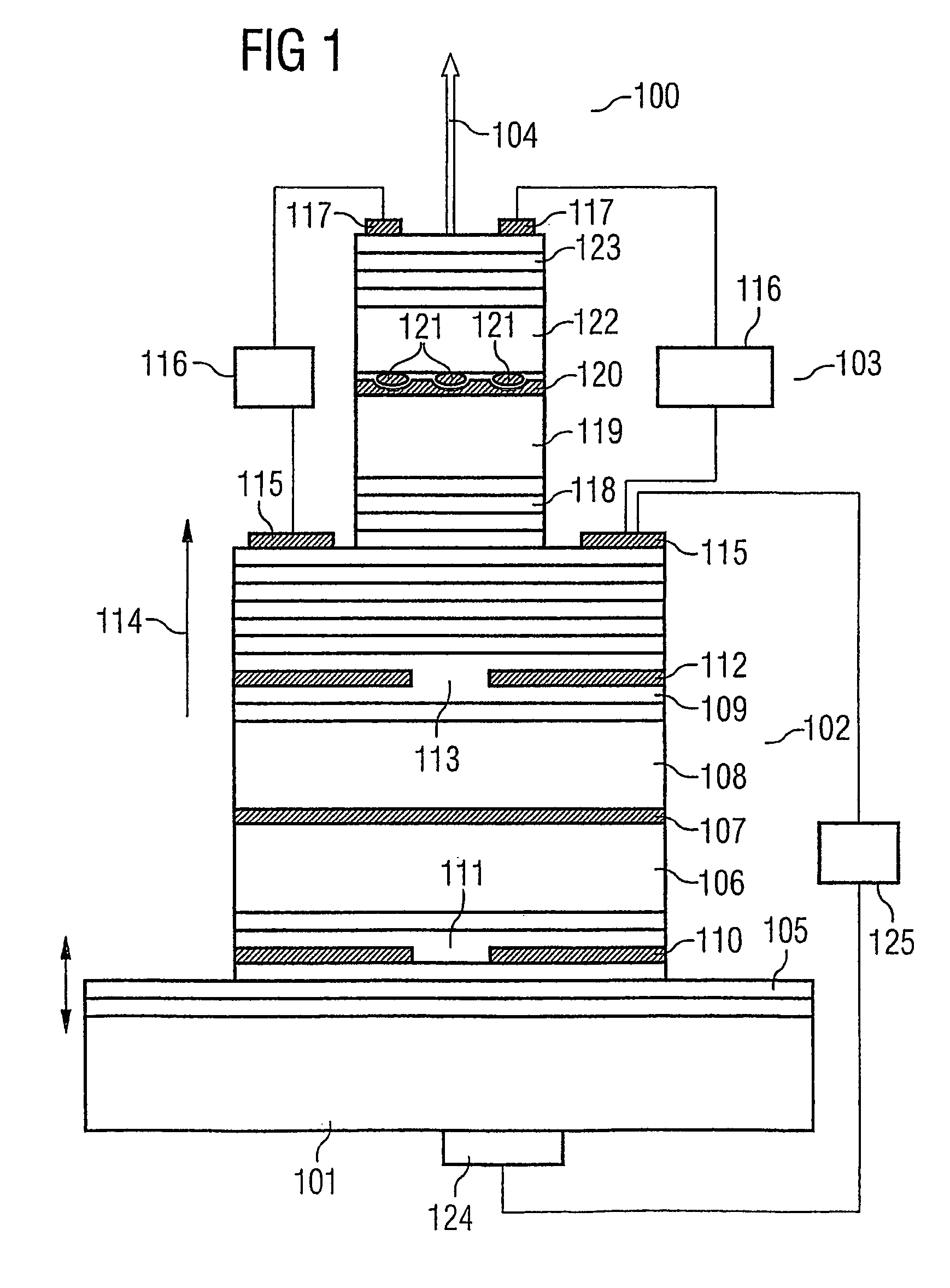
[0046]FIG. 1 shows a cross-sectional view of a photon emitter 100 in accordance with a first exemplary embodiment of the invention.

[0047]A first resonator 102 whose structure will be explained in more detail below is applied to a substrate 101 made from gallium arsenide with a thickness of up to half a millimeter, fundamentally of arbitrary thickness.

[0048]A second resonator 103, which is likewise explained in more detail below, is applied to the first resonator, which is configured as a vertically emitting laser element, this being done in such a way that individual photons can emit in a direction of emission symbolized by an arrow 104.

[0049]The first resonator 102 has as vertically emitting laser element a first reflector layer, configured as a Bragg reflector of a thickness between from one to two μm, as a function of the wavelength of the light beam to be emitted by the laser element, generally with a layer thickness of an individual layer of the Bragg reflector of a quarter of ...


PUM


Abstract

Photon emitter and data transmission device wherein a second resonator is arranged in a direction of emission of a radiation-emitting first resonator in such a way that a quantum dot contained in the second resonator can be excited by energy of radiation emitted by the first resonator. A control unit brings the excitation ground state of the quantum dot into resonance with a prescribed resonator mode of the second resonator.

Description

CROSS-REFERENCE TO RELATED APPLICATIONS[0001]This application is a continuation of International Patent Application Serial No. PCT / DE02 / 01895, filed May 23, 2002, which published in German on Jan. 3, 2003 as WO 03 / 001636 A1.FIELD OF THE INVENTION[0002]The present invention relates to a photon emitter and a data transmission device with a photon emitter, which is suitable to emit single photons on demand at relatively high temperatures.BACKGROUND OF THE INVENTION[0003]Such a photon emitter is known from J. Kim et al., “A Single Photon-Turnstile Device, Letters to Nature,” Vol. 397, pages 500–503, February 1999.[0004]In the case of this component known from J. Kim et al., it was described that individual photons with a frequency of 10 MHz can be emitted at an operating temperature of 50 mK. The photon emitter in accordance with J. Kim et al. is a component which has a mesoscopic double barrier pn heterojunction with a quantum film as active layer for emitting the photons. This photon ...

Claims


Application Information

Patent Timeline
Patent Type & Authority Patents(United States)
IPC IPC(8): H01L33/00H01S5/04H01S5/062H01S5/183H01S5/34
CPCB82Y20/00H01S5/041H01S5/1833H01S5/026H01S5/426H01S5/3412H01S5/0614
Inventor MICHLER, PETER
Owner INFINEON TECH AG
Why Eureka
Try Eureka