CPP-type magnetic head with less deformation and a magnetic recording/reproducing system using the same

a magnetic head and less deformation technology, applied in the field of magnetic heads, can solve the problems of low yield, difficulty in reducing the shield to shield distance to 70 nm or less, and still have problems to be solved, and achieve the effect of high yield and high outpu

Inactive Publication Date: 2006-04-18
HITACHI GLOBAL STORAGE TECH JAPAN LTD +1
View PDF9 Cites 29 Cited by
  • Summary
  • Abstract
  • Description
  • Claims
  • Application Information

AI Technical Summary

Benefits of technology

[0015]It is an object of the present invention to provide a magnetoresistive head having a CPP structure which comprises a CPP magnetoresistive film such as a TMR film or CPP-GMR film at a high yield, wherein the magnetoresistive head is little damaged by mechanical polishing and has high output when air bearing surface processing for achieving a predetermined sensor height is carried out by mechanical processing.
[0016]It is another object of the present invention to provide a magnetic recording / reproducing system having high linear recording density and high areal recording density and incorporating a magnetoresistive head having a CPP structure suitable for a narrow read gap and capable of obtaining high output.

Problems solved by technology

To achieve a narrower shield to shield distance, in the case of a so-called CIP (Current Into the Plane) GMR film in which a sensing current is applied to the plane of a magnetoresistive film, as the thickness of an insulating gap layer interposed between shield layers and the GMR film and between shield layers and electrode films for supplying a sensing current to the GMR film become small and a sensing current leaks out into the shield layer, when the shield to shield distance is set to about 80 nm or less, the yield greatly lowers, and it is technically difficult to reduce the shield to shield distance to 70 nm or less.
Since the CPP structure is a new structure unlike the CIP structure whose technology is becoming mature, it still has some problems to be solved.
One of the problems is a air bearing surface processing technology.
However, the step of obtaining a desired sensor height using the plasma process disclosed by JP-A 11-175927 in air bearing surface processing has a poor throughput, is not practical and needs mechanical polishing.
Therefore, the main cause of deteriorating properties during air bearing surface processing is the shield layer.
More specifically, when a air bearing surface is to be polished, a metal constituting the shield layer is dragged from the insulating gap film to the GMR film, thereby causing a phenomenon that a sensing current leaks out from the GMR film into the shield layer to greatly reduce output.
However, as the magnetoresistive film, the gap layer and the shield layer are made from a metal in the CPP structure head, all of them are readily deformed, whereby the dragging of a metal constituting the shield layer which occurs in the CIP structure head occurs, and also the deterioration of characteristics is caused by the deformation of the gap layer and the deformation of the magnetoresistive film (disorder and fault of the laminate structure).
Therefore, in the case of the CPP structure head, taking the mechanical properties of only the shield layer into consideration is unsatisfactory, and it is important that the magnetoresistive film, the gap layer and the shield layer should be entirely made difficult to be deformed.

Method used


Image

  • CPP-type magnetic head with less deformation and a magnetic recording/reproducing system using the same
  • CPP-type magnetic head with less deformation and a magnetic recording/reproducing system using the same
  • CPP-type magnetic head with less deformation and a magnetic recording/reproducing system using the same

Examples


embodiment 1

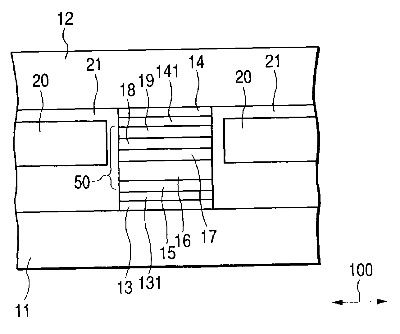
[0074]In Embodiment 1, the lower first deformation prevention layer 13 and the upper first deformation prevention layer 14 have substantially the same width in the track direction as the CPP magnetoresistive film 50. In this embodiment shown in FIG. 5, they have a larger width than the CPP magnetoresistive film 50. The lower first deformation prevention layer 13 can be made as wide as the lower shield layer 11 and the upper first deformation prevention layer 14 can be made as wide as the upper shield layer 12.

[0075]One example of the production process is as follows. After the lower shield layer 11 is formed, the lower first deformation prevention layer 13 is formed and patterned to a desired shape by a dry etching method or ion milling method. The CPP magnetoresistive film 50 is formed, a lift-off mask is formed at a position which becomes a magnetic sensing portion, and the upper gap layer and the CPP magnetoresistive film excluding the magnetic sensing portion are etched by the i...

embodiment 3

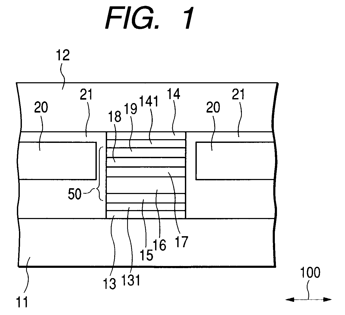
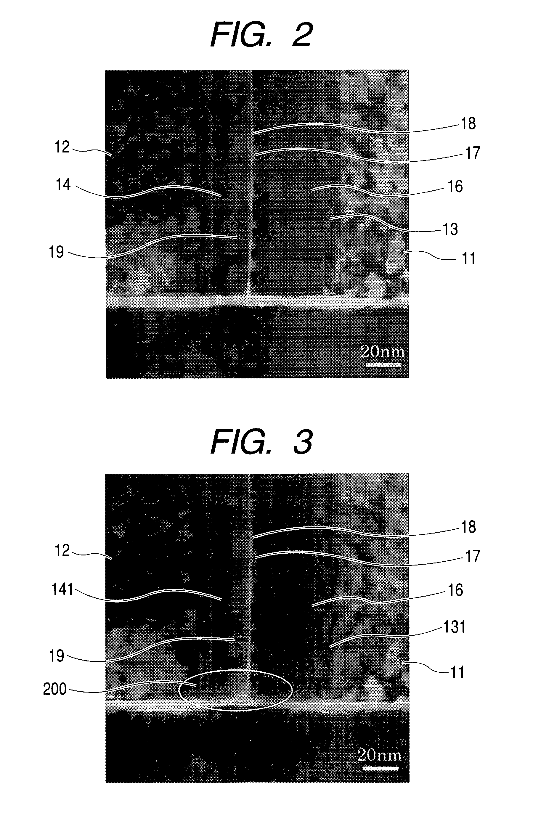
[0080]FIG. 7 shows the structure of the air bearing surface in an embodiment having another longitudinal biasing method of the present invention. After, the lower first deformation prevention layer 13 and CPP magnetoresistive film 50 consisting of a seed layer 15, antiferromagnetic layer 16, second ferromagnetic layer 17, tunnel barrier layer 18 and first ferromagnetic layer 19 are formed on the lower shield layer 11, an underlayer of longitudinal biasing layer 22 made from Cu, Ta or Ru, or a laminate consisting of these layers, longitudinal biasing soft magnetic layer 23 made from a Ni—Fe alloy, a Co—Fe alloy, Fe or a laminate film consisting of these layers, a pinning layer for longitudinal biasing 24 consisting of a Mn—Ir-based antiferromagnetic layer or CoCrPt-based hard magnetic layer, and the lower portion 142 of the upper first deformation prevention layer are formed. A lift-off mask is formed at a position which becomes a magnetic sensing portion and etching is carried out b...

embodiment 7

[0093]When the lower first deformation prevention layer 13 and the upper first deformation prevention layer 14 having a high shear modulus are used in combination in this embodiment like Embodiment 7, the process margin of air bearing surface processing can be made wider.

[0094]FIG. 11 shows that the lower shield layer and the upper shield layer are each a five-layered structure consisting of soft magnetic layers and second formation prevention layers. This is a specific example of this embodiment and may be a three-layered structure, or a laminate structure consisting of a larger number of layers or an even number of layers.

[0095]A single shield layer is used in Embodiment 7. As shown in FIG. 12, the lower shield layer is made a laminate structure consisting of a lower shield layer 11 made from a commonly used material such as a Ni—Fe alloy and formed on the substrate side, a second deformation prevention layer 113 made from Mo which is a material having a high shear modulus and a l...


PUM

PropertyMeasurementUnit
shear modulusaaaaaaaaaa
magnetizationaaaaaaaaaa
heightaaaaaaaaaa

Abstract

A high output, magnetoresistive head with a CPP structure is disclosed which reduces or prevents deformation near the air bearing surface of the read element portion layer at the time of air bearing surface processing. In the CPP structure magnetoresistive head, the deformation near the air bearing surface as a result of mechanical polishing during the air bearing surface processing can be reduced by forming deformation prevention layers having a higher shear modulus than a first ferromagnetic layer, and a second ferromagnetic layer between a magnetoresistive film and at least one of a lower shield layer and an upper shield layer.

Description

BACKGROUND OF THE INVENTION[0001]1. Field of the Invention[0002]The present invention relates to a magnetic head having a CPP (Current Perpendicular to the Plane) structure in which a sensing current is applied in a direction substantially perpendicular to the interface between the first ferromagnetic layer and the intermediate layer of a magnetoresistive film and the interface between the intermediate layer and the second ferromagnetic layer of the film and to a magnetic recording / reproducing system having the magnetic head.[0003]2. Description of the Related Art[0004]Surprisingly, the recording density of a magnetic recording / reproducing system has been increasing at an annual rate of 100%. Along with this, a magnetic head mounted to a magnetic recording / reproducing system is required to have higher output and a narrower shield to shield distance.[0005]To achieve higher output, attempts have been made to improve the performance of a magnetoresistive film. An anisotropic magnetores...

Claims


Application Information

Patent Timeline
Patent Type & Authority Patents(United States)
IPC IPC(8): G11B5/127G11B5/10G11B5/31G11B5/39G11B5/40H01L43/08
CPCB82Y10/00B82Y25/00G11B5/398G11B5/3903G11B5/3909G11B5/3912G11B5/3169G11B5/102G11B5/3106G11B5/3133G11B5/3163G11B5/40G11B2005/3996
Inventor WATANABE, KATSUROKUSUKAWA, KIKUOSHINTANI, TAKUMEGURO, KENICHI
Owner HITACHI GLOBAL STORAGE TECH JAPAN LTD
Why Eureka
Try Eureka