System for monitoring cell motility in real-time

a real-time, cell-based technology, applied in the field of real-time cell-based motility monitoring system, can solve the problems of time-consuming, labor-intensive, expensive, labor-intensive protocol of transwell-based assays, and is not readily adaptable to high-throughput screening and processing,

Inactive Publication Date: 2006-04-25
SURFACE LOGIX INC
View PDF84 Cites 53 Cited by
  • Summary
  • Abstract
  • Description
  • Claims
  • Application Information

AI Technical Summary

Benefits of technology

[0058]In yet another embodiment, an assay comprises positioning a first layer to be in fluid-tight contact with a support, the first layer having an upper surface and defining a pattern of micro-orifices, each micro-orifice of the pattern of micro-orifices having walls and defining a micro-region on the support when the first layer is placed in fluid-tight contact with the support such that the walls of said each micro-orifice and the micro-region on the support together define a micro-well; immobilizing at least one cell of a plurality of cells in each respective micro-region on the support so as to situate the at least one cell within a corresponding micro-well, the cells thereby being arrayed on the support in a pattern that corresponds to the pattern of the micro-orifices; allowing the cells to grow to confluency within the micro-regions; removing the first layer from the support after the step of immobilizing; positioning a second layer to be in fluid-tight contact with the support, the second layer defining a pattern of macro-orifices, each macro-orifice of the pattern of macro-orifices having walls and defining a macro-region when the second layer is placed in fluid-tight contact with the support such that the walls of the macro-orifice and the macro-region together define a macro-well; each macro-region encompassing at least one micro-region; providing at least one of a plurality of test agents to at least one macro-well and allowing said test agent to contact confluent cells; removing said second layer; monitoring cells for movement or lack of movement away from said micro-regions; correlating cellular movement or lack of movement away from said micro-regions with effect of said test agent on cellular movement.
[0059]Another embodiment comprises the steps of: positioning a first layer to be in fluid-tight contact with a support, the first layer having an upper surface and defining a pattern of micro-orifices, each micro-orifice of the pattern of micro-orifices having walls and defining a micro-region on the support when the first layer is placed in fluid-tight contact with the support such that the walls of said each micro-orifice and the micro-region on the support together define a micro-well; positioning a second layer to be in fluid-tight contact with the support, the second layer comprising a plurality of rings, the rings defining a pattern of respective macro-orifices, each ring having walls and defining a macro-region when the second layer is placed in fluid-tight contact with the support such that the walls of the ring and the macro-region together define a macro-well; each macro-region encompassing at least one micro-region; immobilizing at least one cell-of a plurality of cells in each respective micro-region on the support so as to situate the at least one cell within a corresponding micro-well, the cells thereby being arrayed on the support in a pattern that corresponds to the pattern of the micro-orifices, allowing the cells to grow to confluency within the micro-regions; providing at least one of a plurality of test agents to at least one macro-well and allowing said test agent to contact confluent cells; removing said first and second layer; monitoring cells for movement or lack of movement away from said micro-regions; and correlating cellular movement or lack of movement away from said micro-regions with effect of said test agent on cellular movement.
[0060]In an alternate embodiment, an assay for monitoring cell movement comprises the steps of: positioning a layer to be in fluid-tight contact with the support, the layer defining a pattern of macro-orifices, each macro-orifice of the pattern of macro-orifices having walls and defining a macro-region when the layer is placed in fluid-tight contact with the support such that the walls of the macro-orifice and the macro-region together define a macro-well; inserting each plug of a set of plugs in a respective macro-well, each of the plugs comprising a lower membrane placed in fluid-tight contact with the support when the layer is placed in fluid-tight contact with the support and the plug is received in a corresponding macro-well defined by the layer and the support, the lower membrane further defining a pattern of micro-orifices, wherein each micro-orifice has walls and defines a micro-region on the support when the plug is in fluid-tight contact with the support such that the walls of the micro-orifice and the micro-region together define a micro-well; immobilizing a cell in at least one micro-region on the support so as to be situated within the micro-well, such that the cell is arrayed on the support in a pattern that corresponds to the first pattern of micro-orifices; allowing the cells to grow to confluency within the micro-regions; providing at least one of a plurality of test agents to at least one macro-well and allowing said test agent to contact confluent cells; removing said layer containing said plugs; monitoring cells for movement or lack of movement away from said micro-regions; and correlating cellular movement or lack of movement away from said micro-regions with effect of said test agent on cellular movement.
[0061]The present invention also provides for a system for monitoring cell movement comprising: a) a device for arraying cells comprising a support; a first layer configured to be placed in fluid-tight contact with the support, the first layer having an upper surface and defining a pattern of micro-orifices, each micro-orifice of the pattern of micro-orifices having walls and defining a micro-region on the support when the first layer is placed in fluid-tight contact with the support such that the walls of said each micro-orifice and the micro-region on the support together define a micro-well; a second layer configured to be placed in fluid-tight contact with the upper surface of the first layer, the second layer defining a pattern of macro-orifices, each macro-orifice of the pattern of macro-orifices having walls and defining a macro-region when the first layer is placed in fluid-tight contact with the support and the second layer is placed in fluid-tight contact with the first layer such that the walls of the macro-orifice and the macro-region together define a macro-well; wherein the first layer and the second layer are configured for an arraying of cells on the support through the pattern of micro-orifices and the pattern of macro-orifices; allowing the cells to grow to confluency within the micro-regions; providing at least one of a plurality of test agents to at least one macro-well and allowing said test agent to contact confluent cells; removing said first and second layer; monitoring cells for movement or lack of movement away from said micro-regions; and correlating cellular movement or lack of movement away from said micro-regions with effect of said test agent on cellular movement; b) an observation system configured to observe movement or lack of movement of arrayed cells; and c) a controller configured to link coordinates movement of the device for arraying cells into said observation system.

Problems solved by technology

For instance, assays employing transwells require a labor-intensive protocol that is not readily adaptable to high-throughput screening and processing.
The counting of cells, which is often done manually using a microscope, is a time-consuming, tedious, and expensive process.
Furthermore, cell counting is also subjective and involves statistical approximations.
Notwithstanding the above, perhaps the most significant disadvantage to the use of transwells is that when the cells are fixed to a slide, as required for observation, they are killed.
Consequently, once a cell is observed it can no longer be reintroduced into the assay or studied at subsequent periods of exposure to the stimulus.
Although useful, assays based on cell migration have been limited in use because of the unavailability of convenient tools for performing the assay.
The use of a Boyden Chamber requires a labor-intensive protocol, and it is not readily adaptable to a high-throughput screening process.
The examination and counting of the cells on the filter is time-consuming, tedious, and expensive.
In addition, the time and expense associated with examining the entire filter necessitates that only representative areas, selected at random, be counted, thus rendering the results less accurate than would otherwise be the case if the entire filter were examined and counted.
Perhaps the most important disadvantage in this procedure is that the fixing step kills the cells.
That is, the procedure is destructive of the cell sample.
The time and expense associated with a time-dependent study is usually prohibitive of conducting such a study using the Boyden procedure.
In addition, most of these procedures require fixing and staining the cells, and none of them permit the kinetic or time-dependent study of the chemotactic response of the same cell sample.
Further, these methods involve the counting of cells, a lengthy procedure not compatible with high-throughput applications.
However, because of the inherent complexity of multicellular systems, little is known about how cell migration mediates cellular pattern formation.
These co-cultures have limited use, however, because they represent a mixed population of cells.
The effects of intercellular contact on cell morphology or on a function or protein unique to one of the cell types can be examined; however, investigation of biochemical or molecular processes common to both cells in not possible.
These methods are slow and laborious and as such are not suitable to the demands of high throughput assays.
Current existing techniques require laborious protocols and work as end-point assays.

Method used


Image

  • System for monitoring cell motility in real-time
  • System for monitoring cell motility in real-time
  • System for monitoring cell motility in real-time

Examples


example 1

Procedure for Cell Migration Allay Plate Fabrication

[0272]A topographically patterned master having a plurality of posts is prepared from a photolithographic mask. These posts are elevated approximately 100 μm above the background. In one embodiment, the pattern is made up of 24 micro-regions, each containing a circular array of 200 μm posts spaced on a 500 μm center. Alternately, instead of having discrete regions of posts, the entire surface of the master may contain posts. In one preferred embodiment, the master is made of photoresist patterned on a 150 mm silicon wafer. To prepare this master, SU-850n photoresist spun at 1300 rpm was used and processed according to the supplier's specifications.

[0273]A two-component poly(dimethylsiloxane) (PDMS) prepolymer (Gelest Optical Encapsulant 41) was mixed and degassed under vacuum before it is spun onto the master. This spin coating was done at a speed high enough to produce a polymeric membrane (i.e., the thickness of the resulting PDM...

example 2

Patterning of Cells on a Support

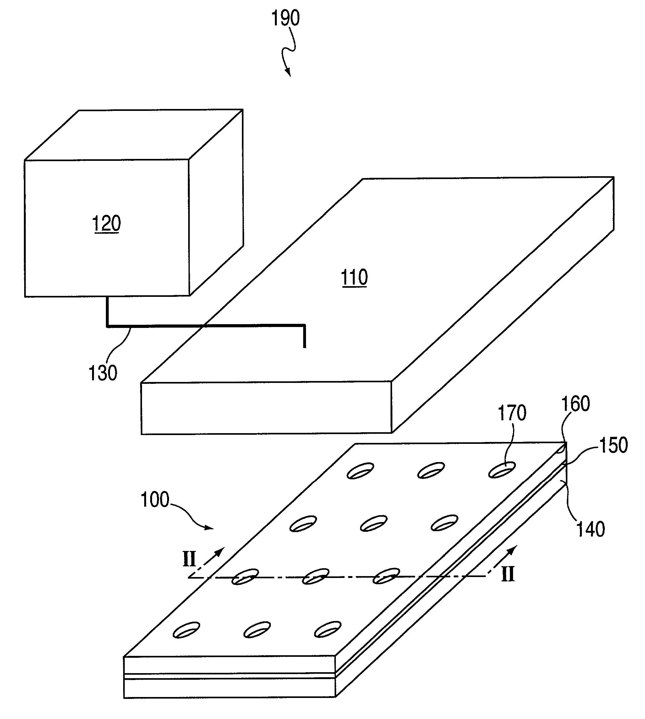
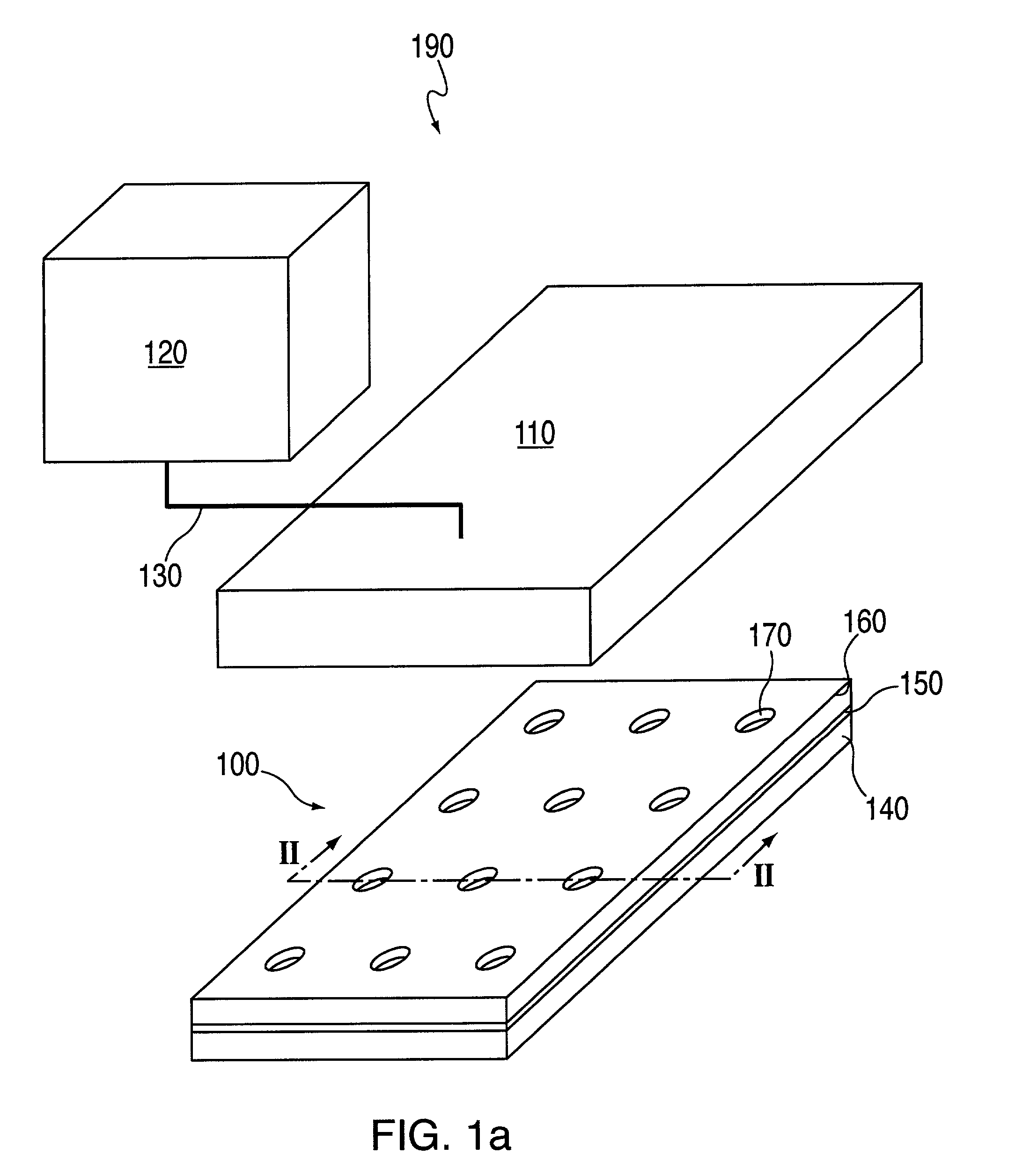
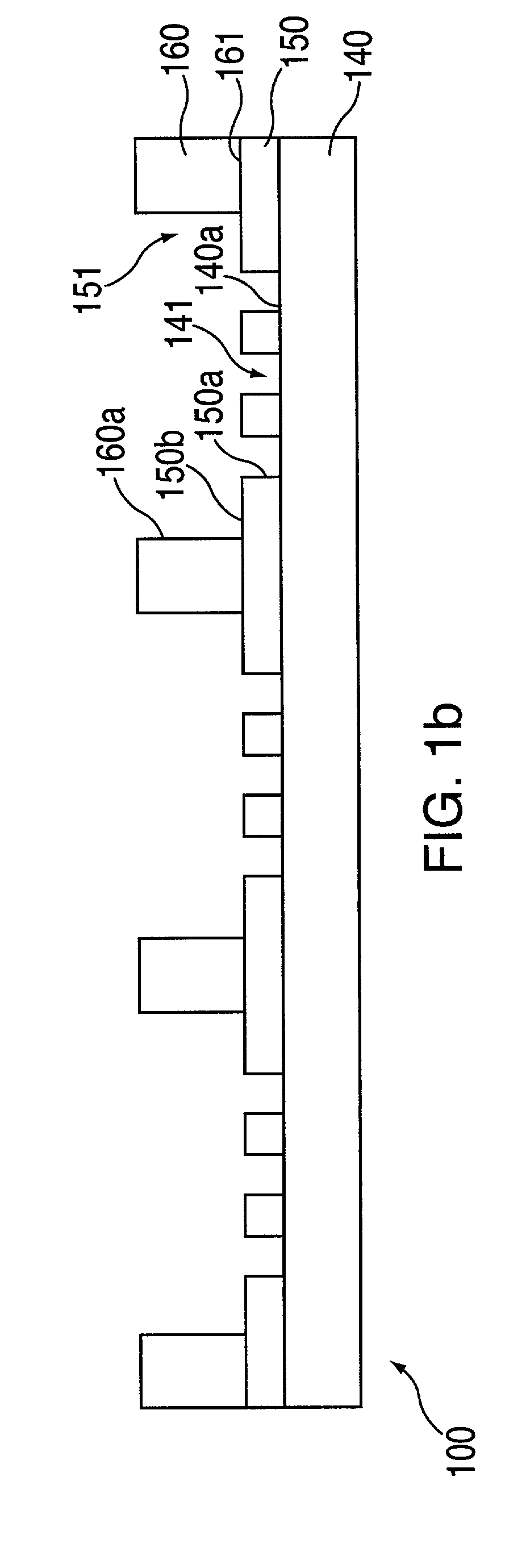
[0278]In this example, macro-wells of a stencil which is engaged with a the first layer 150 and support are filled with PBS and a vacuum is applied for two minutes to remove air bubbles. The support may then be treated with fibronectin (50 mg / ml) or other extracellular matrix protein for 30 minutes, followed by washing twice with PBS. After aspirating PBS, cells may then be plated in freshly warmed medium at a density of 5–25×103 cells / cm2 (=1–4×10⁴ cells per macro-well of a 24-well plate 100, in a volume of 300 ml per macro-well; or 5–25×104 cells per 35 mm dish in a volume of 2 ml). The cells deposit through the micro-orifices of the first layer, and attach to the support.

[0279]After the cells have attached to the support (30 minutes-2 hours), the cell culture medium in each macro-well is replaced with fresh medium. Cells are left to spread in a 37° C. incubator for two hours to overnight. The cells are washed with PBS and fresh medium containing th...

example 3

Image Acquisition

[0280]Imaging is performed using an inverted microscope equipped with the following: epifluorescence, motorized and programmable stage, autofocus mechanism, and CCD camera. Two to three randomly selected areas per macro-well are imaged. The stage translated from one macro-well to another, and images were focused using automatic focus (Z axis). Images were captured in either phase contrast or epifluorescence.

[0281]Acquired images shared a common file name, but different suffix corresponding to the macro-well number and position. For example, an experiment called TEST with 24 wells generated TEST01-TEST24 when one image per macro-well was taken. Images are generated prior to application of a test compound or other external stimulus, and at various times after treatment.


PUM

PropertyMeasurementUnit
diameteraaaaaaaaaa
diameteraaaaaaaaaa
diameteraaaaaaaaaa

Abstract

The invention relates to devices, devices for arraying biomolecules, including cells, methods for arraying biomolecules, assays for monitoring cellular movement, and systems for monitoring cellular movement. The devices include a support; a first layer configured to be placed in fluid-tight contact with the support, the first layer having an upper surface and defining a pattern of micro-orifices, each micro-orifice of the pattern of micro-orifices having walls and defining a micro-region on the support when the first layer is placed in fluid-tight contact with the support such that the walls of said each micro-orifice and the micro-region on the support together define a micro-well; and a second layer configured to be placed in fluid-tight contact with the upper surface of the first layer, the second layer defining a pattern of macro-orifices, each macro-orifice of the pattern of macro-orifices having walls and defining a macro-region when the first layer is placed in fluid-tight contact with the support and the second layer is placed in fluid-tight contact with the first layer such that the walls of the macro-orifice and the macro-region together define a macro-well.

Description

RELATED APPLICATIONS[0001]This application is a continuation in part of U.S. application Ser. No. 09 / 709,776, filed on Nov. 8, 2000, now U.S. Pat. No. 6,699,665. This application also claims the benefit of and incorporates herein by reference, in their entirety: U.S. Provisional Application No. 60 / 307,886, filed on Jul. 27, 2001; U.S. Provisional Application No. 60 / 323,742, filed on Sep. 21, 2001; U.S. Provisional Application No. 60 / 328,103, filed on Oct. 11, 2001; U.S. Provisional Application No. 60 / 330,456, filed on Oct. 22, 2001; U.S. Provisional Application No. 60 / 334,548, filed on Dec. 3, 2001; U.S. Provisional Application No. 60 / 363,355, filed on Mar. 12, 2002; and U.S. Provisional Application No. 60 / 374,799, filed on Apr. 24, 2002.FIELD OF THE INVENTION[0002]The invention generally relates to devices and methods for patterning cells in a predetermined array for subsequent observation and measurement of cell motility.BACKGROUND[0003]The study of cellular behavior and the effec...

Claims


Application Information

Patent Timeline
Patent Type & Authority Patents(United States)
IPC IPC(8): C12M1/36B01L3/00C12M3/00C40B40/06C40B40/10C40B60/14G01N33/543G06T7/00
CPCB01L3/5025B01L3/5085B82Y15/00B82Y30/00B82Y40/00C12M23/12C12M25/06C12M41/46C12Q1/025G01N33/5029G01N33/54366G06K9/00127G06K9/0014G06T7/0012G06T7/004B01D2325/08G06T2207/30072B01J2219/00662B01J2219/00722B01J2219/00725B01J2219/00743B01L3/5027B01L2200/0647B01L2200/12B01L2300/0636B01L2300/0829B01L2300/0887C40B40/06C40B40/10C40B60/14G01N15/1468G01N2015/1497B01J2219/00317G06T7/70G06V20/69G06V20/695
Inventor KIM, ENOCHKIRK, GREGORY L.SCHUELLER, OLIVIEROSTUNI, EMANUELE
Owner SURFACE LOGIX INC
Why Eureka
Try Eureka