
Apparatus for reducing plasma charge damage for plasma processes

a technology of plasma discharge and plasma discharge, which is applied in the direction of electric discharge tubes, chemical vapor deposition coatings, coatings, etc., can solve the problems of increasing the damage of metal-line charging and gate oxides, the damage of destructive currents during plasma-enhanced etching processes, and the damage of metal-line discharges. , to achieve the effect of reducing the incidence of plasma discharge damage and reducing the damage of plasma discharg

Inactive Publication Date: 2006-05-02
APPLIED MATERIALS INC
View PDF9 Cites 302 Cited by
  • Summary
  • Abstract
  • Description
  • Claims
  • Application Information

AI Technical Summary

Benefits of technology

[0011]The disadvantages of the prior art are overcome with a method for reducing plasma discharge damage during plasma deposition processes. By configuring the gas flows to a process chamber such that deposition on a wafer proceeds more rapidly at the center of the wafer than at the edges, the incidence of plasma charge damage is reduced. Accordingly, in one embodiment, a method is provided for depositing a thin film on a substrate in a process chamber. The method comprises flowing a process gas containing a plurality of precursor gases suitable for forming a plasma into the process chamber, and generating a plasma from the process gas to deposit the thin film on the substrate. The precursor gases are flowed into the process chamber such that the thin film is deposited at the center of the substrate more rapidly than at an edge of the substrate.

Problems solved by technology

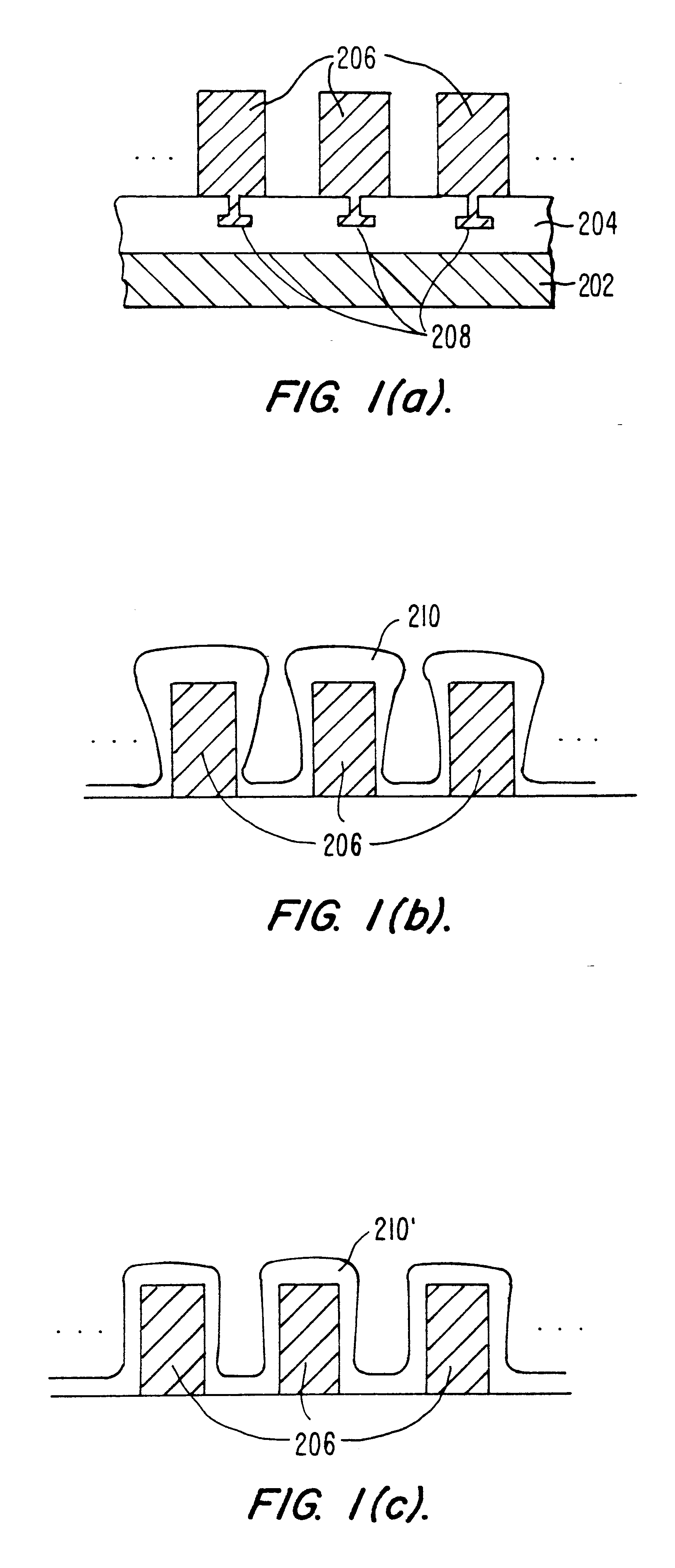
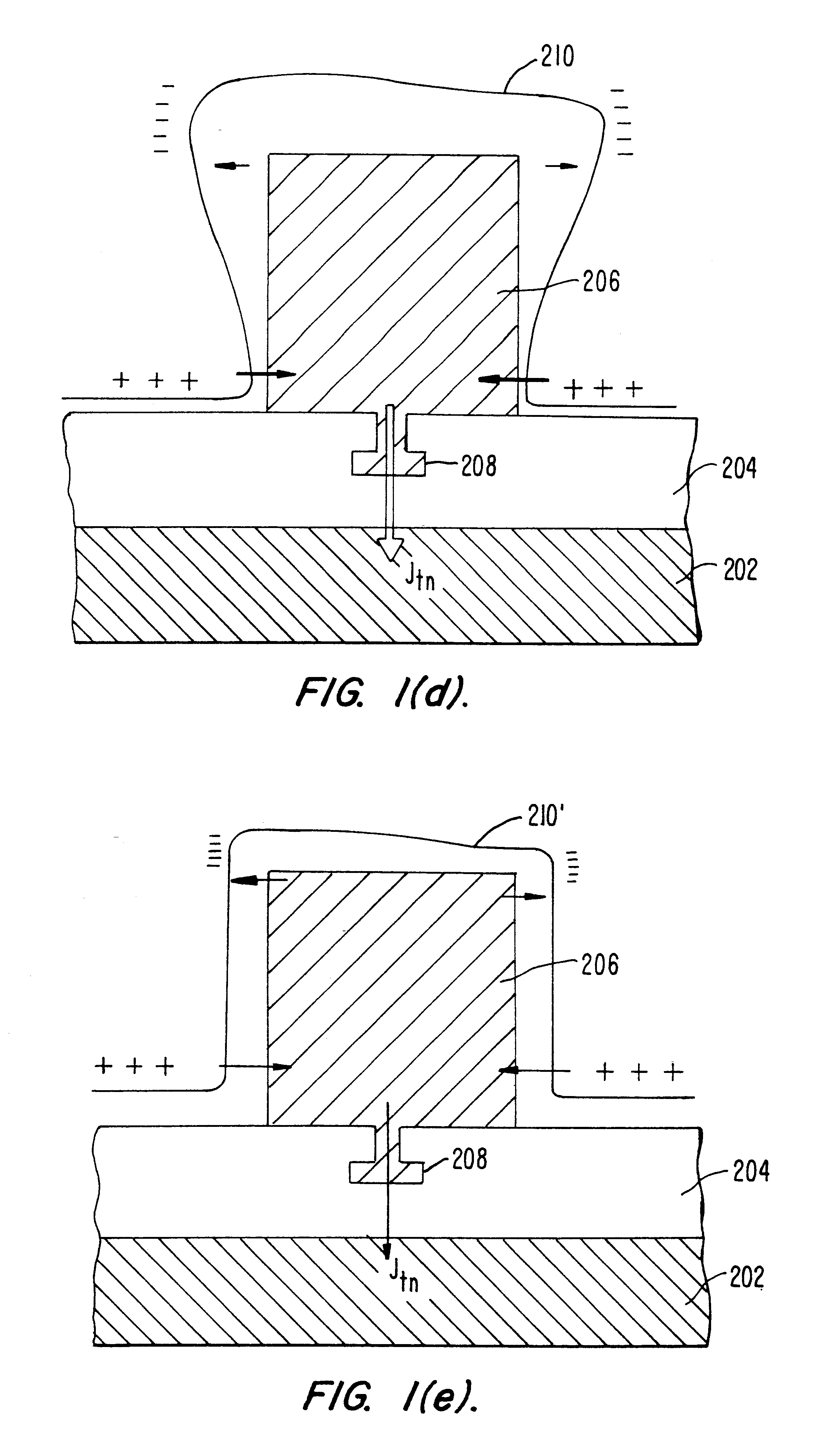
It is this thickness dependence that causes deposition of a nonconformal oxide to result in greater metal-line charging and increased gate oxide damage, as shown in FIG.
Moreover, while the description has focused on the generation of currents during deposition, similarly destructive currents are generated during plasma-enhanced etching processes.
As a result, both deposition and etching processes that use plasma processes to form integrated circuit structures can damage microstructure components by, e.g., causing sidewall irregularities (notching, bowing, etc.) and / or latent gate oxide degradation.

Method used


Image

  • Apparatus for reducing plasma charge damage for plasma processes
  • Apparatus for reducing plasma charge damage for plasma processes
  • Apparatus for reducing plasma charge damage for plasma processes

Examples


Embodiment Construction

I. Introduction

[0042]Fabrication of integrated circuits is typically performed on a circular wafer made of a semiconductor such as silicon. A plurality of rectilinear devices is formed on the wafer as a rectangular array, leaving four similarly shaped circular segments that remain unprocessed. Embodiments of the invention are directed to reducing the possibility of plasma charge damage to such circuits by using a plasma deposition process that begins covering the center of the wafer and works the deposition outwards towards the wafer's edge. The presence of the initial dielectric film at the wafer center prevents destructive charging. In other embodiments, the technique is adapted for etching processes in addition to deposition processes.

II. Exemplary Substrate Processing System

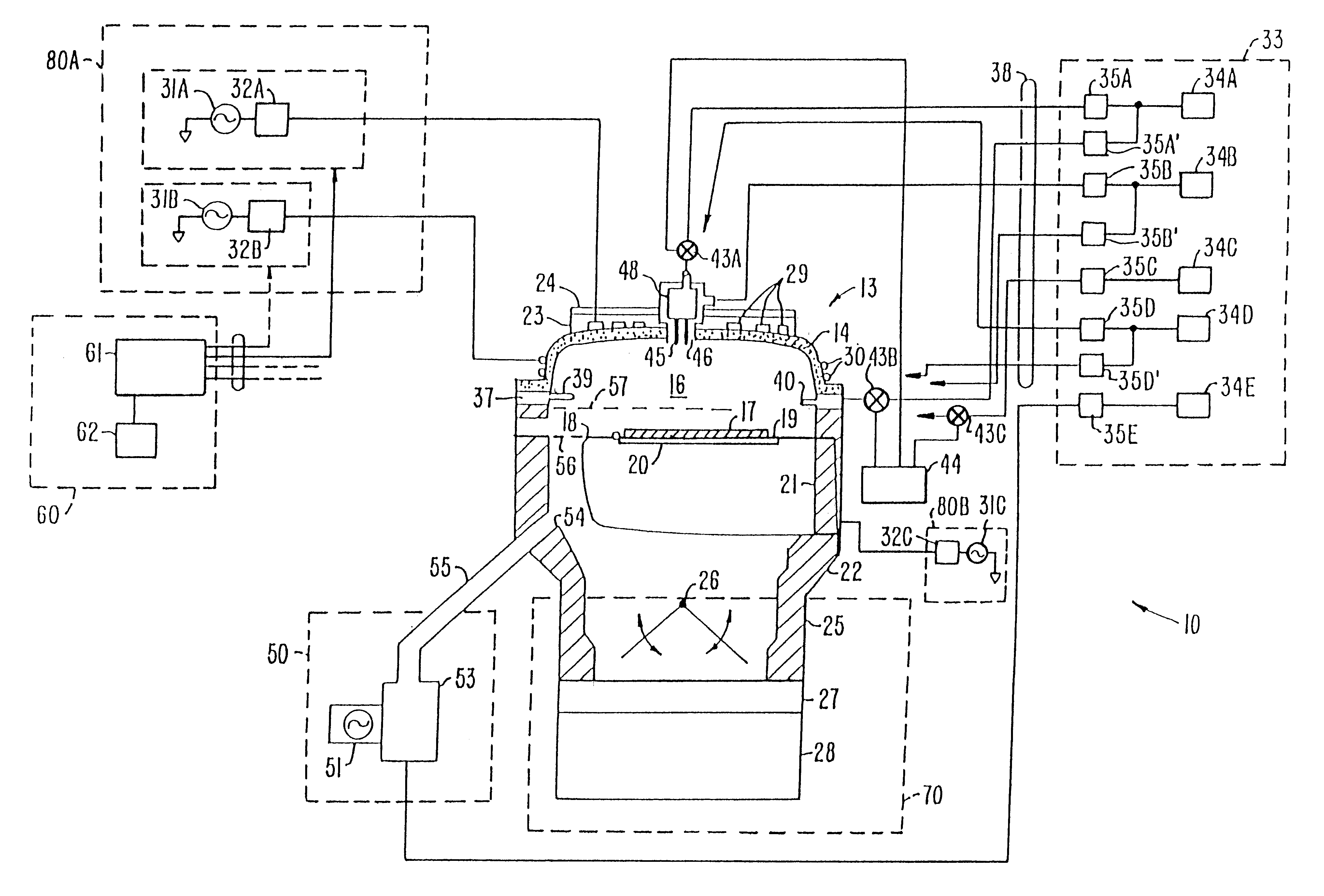
[0043]FIG. 2A illustrates one embodiment of a high density plasma chemical vapor deposition (HDP-CVD) system 10 in which a dielectric layer according to the present invention can be deposited. System 10 inclu...


PUM

PropertyMeasurementUnit
Electric potential / voltageaaaaaaaaaa
Flow rateaaaaaaaaaa

Abstract

A method is provided for depositing a thin film on a substrate in a process chamber with reduced incidence of plasma charge damage. A process gas containing a precursor gases suitable for forming a plasma is flowed into a process chamber, and a plasma is generated from the process gas to deposit the thin film on the substrate. The precursor gases are flowed into the process chamber such that the thin film is deposited at the center of the substrate more rapidly than at an edge of the substrate.

Description

[0001]This application is a divisional application of U.S. Patent Application Ser. No. 09 / 771,203 filed Jan. 26, 2001, now U.S. Pat. No. 6,660,662 the entire disclosure of which is incorporated herein by reference.BACKGROUND OF THE INVENTION[0002]The present invention relates to the manufacture of integrated circuits on a substrate. More particularly, the invention relates to a method and apparatus for reducing plasma charge damage when such integrated circuits are manufactured using a plasma processing technique.[0003]One of the steps in the fabrication of modern semiconductor devices is the formation of a thin film on a semiconductor substrate by chemical reaction of gases. Such a deposition process is referred to as chemical vapor deposition (“CVD”). Conventional thermal CVD processes supply reactive gases to the substrate surface where heat-induced chemical reactions take place to produce a desired film. Plasma-enhanced CVD techniques, on the other hand, promote excitation and / o...

Claims


Application Information

Patent Timeline
IPC IPC(8): C23C16/00C23C16/52C23C16/455H01L21/205H01L21/302H01L21/31
CPCH01J37/3244C23C16/455C23C16/45559C23C16/505
Inventor ISHIKAWADEMOS, ALEXANDROS T.CHO, SEON-MEEGAO, FENGNIAZI, KAVEH F.ARUGA, MICHIO
Owner APPLIED MATERIALS INC
Learn More