
Photosensitive polyimide resin precursor composition, optical polyimide obtained from the composition, optical waveguide using the polyimide, and process for producing the optical waveguide

a technology of photosensitive polyimide resin and precursor composition, which is applied in the direction of photosensitive materials, instruments, photomechanical apparatuses, etc., can solve the problems of not solving the problem of realizing a reduction of production cost, affecting the effect of sensitivity, and reducing the decomposition of photosensitive compounds

Inactive Publication Date: 2006-05-02
NITTO DENKO CORP
View PDF16 Cites 2 Cited by
  • Summary
  • Abstract
  • Description
  • Claims
  • Application Information

AI Technical Summary

Benefits of technology

The solution achieves a transparent, heat-resistant polyimide resin with reduced light absorption in the near-infrared region, enabling the production of optical waveguides with low light propagation loss and improved manufacturing efficiency, including a square cross-sectional shape for enhanced optical performance.

Problems solved by technology

However, in the case where these polymers are subjected to hybrid integration with a laser diode, a photo diode, etc., their heat resistance in a solder reflow step is not sufficient, and therefore, they involve a defect such that the range of use is very limited.
However, according to such conventional dry process, not only it takes a long period of time to form an optical circuit, but also the problem of realizing a reduction of the production cost is not solved yet because the processing region is restricted.
Further, according to such dry process, since a wall surface (side surface) of the formed pattern is not flat, a scattering loss becomes large during wave guiding of a light into the optical circuit.
However, derived from resolution, adhesiveness and material brittleness of the resist, the side surface of the resulting pattern is not smooth but is found to have fine irregularities.
However, a new problem in light loss of the resulting polyimide resin must be solved.
However, since the polyimide resin by the wet process partly absorbs a light in not only a visible light region but also a near infrared light region, it is hardly used as the optical waveguide material.
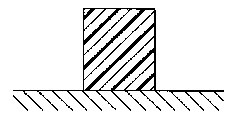
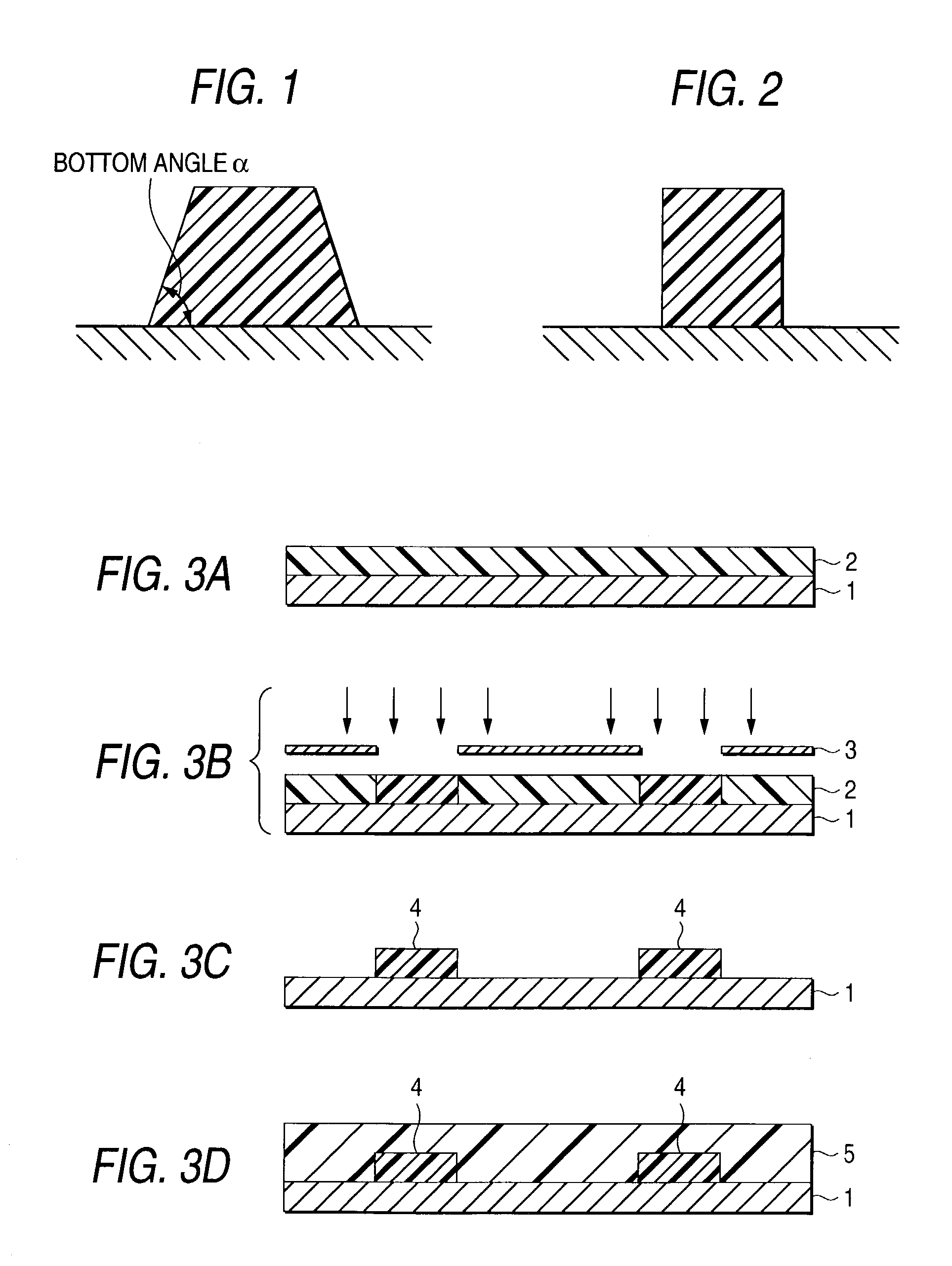
Further, in the case where the polyimide resin by the wet process of the foregoing photosensitive polyimide resin precursor composition is used as an optical waveguide material, especially in the case where it is used as a core layer of the optical waveguide, there is a problem in cross-sectional shape of the pattern, in addition to the problem in light loss.
However, in the most of optical waveguides inclusive of planar lightwave circuits (PLC), it is difficult to make the cross-sectional shape of the core circular due to the manufacturing process thereof.

Method used


Image

  • Photosensitive polyimide resin precursor composition, optical polyimide obtained from the composition, optical waveguide using the polyimide, and process for producing the optical waveguide
  • Photosensitive polyimide resin precursor composition, optical polyimide obtained from the composition, optical waveguide using the polyimide, and process for producing the optical waveguide
  • Photosensitive polyimide resin precursor composition, optical polyimide obtained from the composition, optical waveguide using the polyimide, and process for producing the optical waveguide

Examples


example 1

[0101]In a 500 ml separable flask, 16.7 g (0.05 moles) of 2,2-bis(4-aminophenyl) hexafluoropropane (BAAF) was dissolved in 155.6 g of N,N-dimethylacetamide (DMAc) in a nitrogen atmosphere. 22.2 g (0.05 moles) of 2,2-bis(3,4-dicarboxyphenyl)hexafluoropropane dianhydride was added to this solution with stirring, and the resulting mixture was additionally stirred at room temperature for 24 hours to prepare a polyamic acid solution.

[0102]0.019 g (0.05 parts by weight per 100 parts by weight of the polyamic acid (solids content) of the polyamic acid solution) of EDHP (photosensitive compound) and 5.8 g (15 parts by weight per 100 parts by weight of the polyamic acid of the polyamic acid solution) of polyethylene glycol dimethyl ether having a weight average molecular weight of 500 were added to this polyamic acid solution to obtain a photosensitive polyimide resin precursor composition as a solution.

[0103]The solution of the photosensitive polyimide resin precursor composition was applie...

example 2

[0106]A channel type optical waveguide was obtained in the same manner as in Example 1, except that 2 parts by weight of the photosensitive compound (EDHP) per 100 parts by weight of the polyamic acid (solids content) was used. This optical waveguide was measured for light propagation loss in the same manner as in Example 1. As a result, the optical waveguide had a light propagation loss of 1.4 dB / cm.

example 3

[0107]A channel type optical waveguide was obtained in the same manner as in Example 1, except that 4 parts by weight per 100 parts by weight of the polyamic acid (solids content) of the photosensitive compound (EDHP) was used. This optical waveguide was measured for light propagation loss in the same manner as in Example 1. As a result, the optical waveguide had a light propagation loss of 1.6 dB / cm.


PUM

PropertyMeasurementUnit
aspect ratioaaaaaaaaaa
temperatureaaaaaaaaaa

Abstract

A photosensitive polyimide resin precursor composition capable of providing a polyimide resin that is not substantially colored, is transparent and has heat resistance, an optical polyimide resin obtained from the composition, and an optical waveguide using the polyimide resin. The photosensitive polyimide resin precursor composition contains (a) 100 parts by weight of a polyamic acid obtained from a tetracarboxylic acid dianhydride and a diamine, (b) 0.01 parts by weight or more and less than 5 parts by weight of a 1,4-dihydropyridine derivative, (c) 5–50 parts by weight of a glycol (ether). The optical polyimide resin is obtained by irradiating the photosensitive resin precursor composition with UV light, followed by exposure, heating, development, and then heating. The optical waveguide comprises a core layer comprising the optical polyimide resin, and a cladding layer thereof.

Description

FIELD OF THE INVENTION[0001]The present invention relates to a photosensitive polyimide resin precursor composition, an optical polyimide resin obtained from the composition, an optical waveguide using the polyimide resin, and a process for producing the optical waveguide. Particularly, the invention relates to a photosensitive polyimide resin precursor composition capable of providing a transparent optical polyimide resin having a small birefringent index, which can be suitably used for optical waveguides, optical waveguide devices, optical integrated circuits, optical wirings, etc. as broadly used in optical communication, optical information processing, and other general optical fields, an optical polyimide resin obtained from such a photosensitive polyimide resin precursor composition, a optical waveguide obtained by using such an optical polyimide resin as a core layer, and a process for producing the optical waveguide.DESCRIPTION OF THE RELATED ART[0002]With the progress of pr...

Claims


Application Information

Patent Timeline
Patent Type & Authority Patents(United States)
IPC IPC(8): G03F7/038G02B6/10C08G73/10C08K5/06C08K5/3432C08L79/08G03F7/00G03F7/004
CPCC08K5/06C08K5/3432C08L79/08G03F7/0005G03F7/001G03F7/0045G03F7/0387C08L2666/22A63H1/20A63H33/084
Inventor MUNE, KAZUNORIMOCHIZUKI, AMANEHAYASHI, SHUNICHIFUJII, HIROFUMIFUKUOKA, TAKAHIRONAITOU, RYUSUKE
Owner NITTO DENKO CORP
Learn More