Thin film transistor and multilayer film structure and manufacturing method of same
a technology of thin film transistor and multilayer film, which is applied in the direction of transistors, optics, instruments, etc., can solve the problems of high manufacturing cost and high investment cost, and achieve the effect of reducing the cost of manufacturing such devices, facilitating formation, and reducing investment costs
- Summary
- Abstract
- Description
- Claims
- Application Information
AI Technical Summary
Benefits of technology
Problems solved by technology
Method used
Image
Examples
embodiment 1
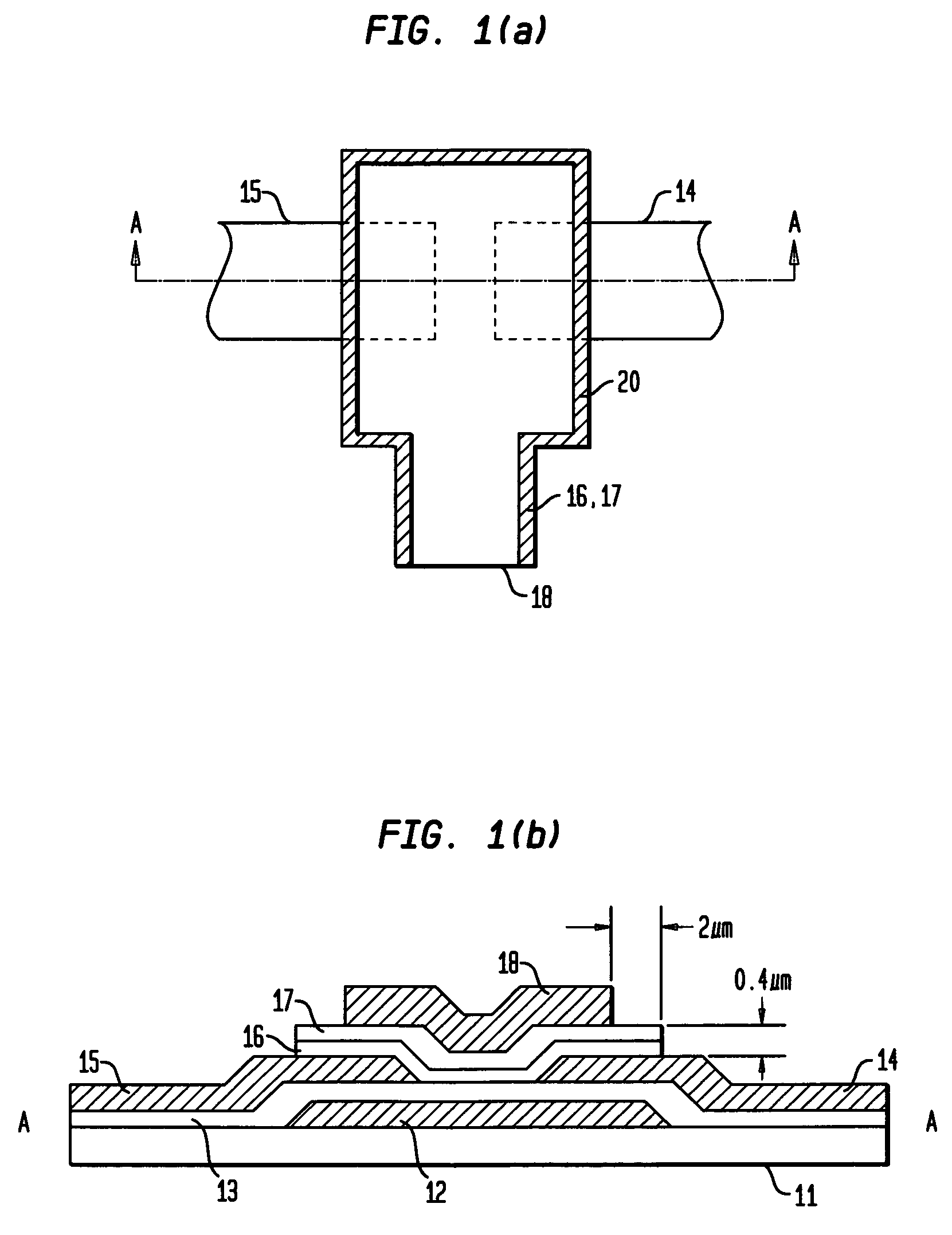
[0025]Each of FIGS. 1(a) and 1(b) is a view showing a thin film transistor (TFT) structure of the present invention, by taking an example of a TFT of a top gate type. Specifically, FIG. 1(a) shows a state of the TFT when seen from above, which is manufactured in a shortened process by a later-described manufacturing method; and FIG. 1(b) shows an A—A section of FIG. 1(a).
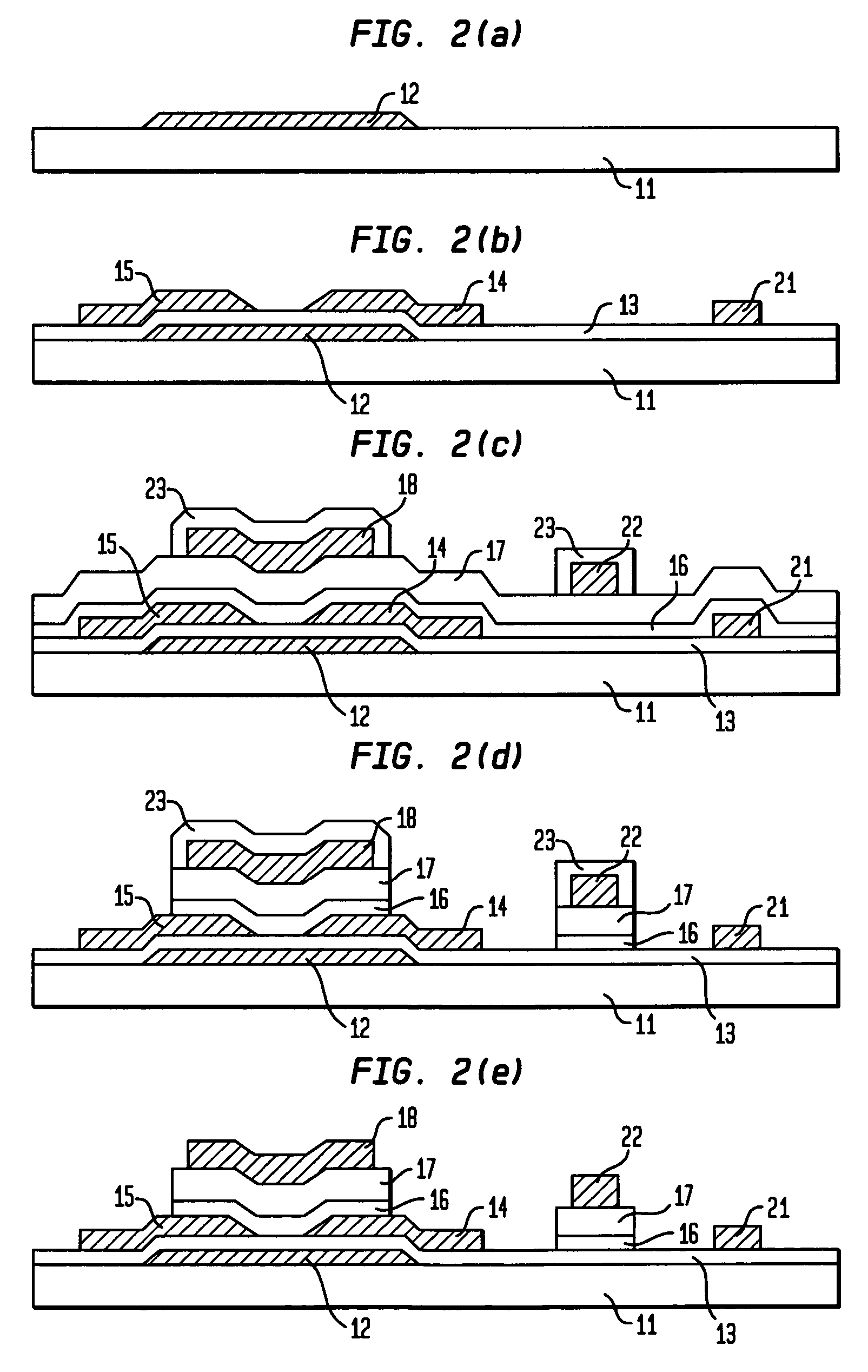
[0026]As shown in FIG. 1(b), the TFT of the embodiment comprises a light shielding film (light shield) 12 formed on an insulating substrate 11 made of no-alkali glass, quartz or the like, and an insulating film 13 formed as an undercoated layer to cover the upper portion thereof, the undercoated layer being made of an oxidized silicon nitride film SiOxNy or the like. Preferably, the light shielding film 12 is formed by printing-and-plating copper (CU). On the insulating film 13, source and drain electrodes 14 and 15 are formed. Preferably, the source and drain electrodes are formed by printing-and-plating cobalt (Co...
second embodiment
[0040]The description above illustrates an embodiment of the present invention in a TFT of a top gate type. Next, description will be made for the present invention in a TFT of a bottom gate type and another multilayer film structure, to which the present invention is applied.
[0041]Each of FIGS. 3(a) and 3(b) is a view illustrating a constitution of this second embodiment. FIG. 3(a) shows the state where the gate electrode 31 and the data line 32 cross to each other. FIG. 3(b) shows a B—B section of FIG. 3(a). In the multilayer film structure of the embodiment, as shown in FIG. 3(b), an a-Si film 34 and a gate insulating film 35 are formed on a gate electrode 31, and a data line 32 is formed on the gate insulating film 35. If an end surface of the data line 32 coincides with an etching end surface of the a-Si film 34 or the gate insulating film 35, then a short circuit may occur between the gate electrode 31 and the data line 32 at a crossing position like that shown in FIG. 3(a). T...
PUM
| Property | Measurement | Unit |
|---|---|---|
| width | aaaaa | aaaaa |
| total height | aaaaa | aaaaa |
| thickness | aaaaa | aaaaa |
Abstract
Description
Claims
Application Information
 - R&D
- Intellectual Property
- Life Sciences
- Materials
- Tech Scout
- Unparalleled Data Quality
- Higher Quality Content
- 60% Fewer Hallucinations
Browse by: Latest US Patents, China's latest patents, Technical Efficacy Thesaurus, Application Domain, Technology Topic, Popular Technical Reports.
© 2025 PatSnap. All rights reserved.Legal|Privacy policy|Modern Slavery Act Transparency Statement|Sitemap|About US| Contact US: help@patsnap.com


