
Parallel-plate capacitive element for monitoring environmental parameters in concrete

Inactive Publication Date: 2006-05-02
ADVANCED DESIGN CONSULTING USA
View PDF6 Cites 190 Cited by
  • Summary
  • Abstract
  • Description
  • Claims
  • Application Information

AI Technical Summary

Benefits of technology

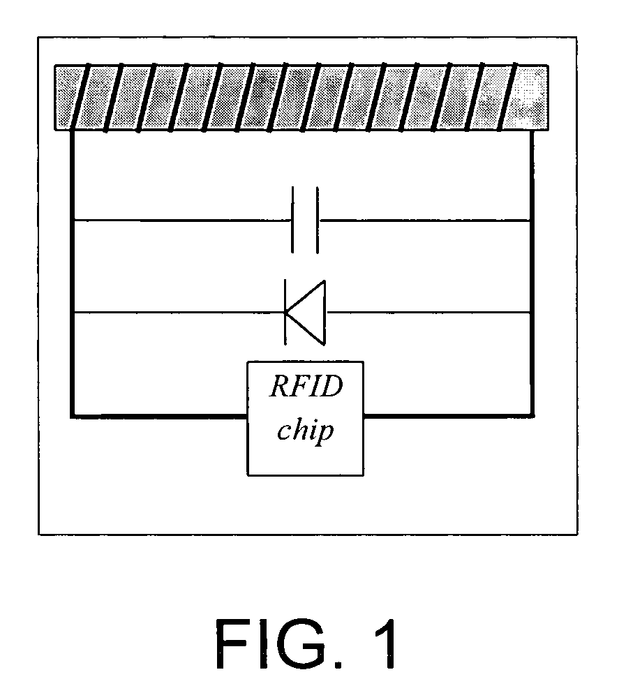
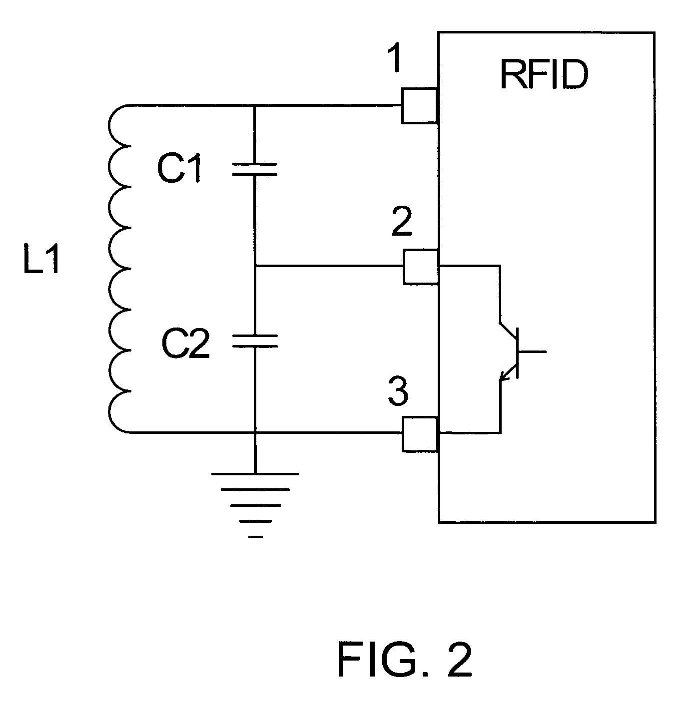
[0047]The present invention provides an embeddable sensor for monitoring concrete condition that can survive for the lifetime of the concrete. The invention is based on the surprising discovery, on the part of the inventors, that a low-cost, efficient, long-lived sensor for monitoring concrete may be constructed that is powered and interrogated using radio frequency (RF) energy from a distance (e.g., a distance of over one meter), and that returns a unique identification signal (e.g., a number) so that data can be correlated with sensor location. According to the invention, operation of the sensor is based on capacitive changes in a MEMS semi-conductor device (e.g., a silicon semi-conductor device) by a change in (e.g., swelling of or change in permittivity of) a material deposited on or in the semi-conductor device. Data obtained from the sensor of the invention is used to prolong the service life of concrete, lower infrastructure costs and promote development of more effective plans for remediation.

Problems solved by technology

One of the most devastating, yet most common, forms of concrete degradation is corrosion of embedded reinforcing steel, which is driven by moisture and temperature as the pH is lowered.
This balance is upset, however, when contaminants such as deicing salts penetrate the concrete or when concrete carbonates, formed by the conversion of calcium hydroxide to calcium carbonate, as CO2 permeates the capillary pores.
While these techniques have been widely accepted, they are time-consuming and expensive.
Electronic moisture sensors have been available for a considerable time, but have inherent limitations when embedded within concrete.
The highly alkali environment can damage their electronics, and they are sensitive to electromagnetic noise.
A further drawback of this approach is that power must be provided from an external source, requiring cables and connectors (e.g., Structural Health Sensor, Strain Monitor Systems, Inc., San Diego, Calif.
This necessarily increases the sensor's size and decreases the sensor's useful life.
The drawback of this approach is that only up to six sensors have been used.
This somewhat decreases the cost of this type of sensor, but this is offset by the sophistication and cost of the equipment required for analysis.
Furthermore, these optical systems all have the drawbacks that they require laser sources and optical power meters for measurements, as well as sophisticated analysis, if multiple sensors are to be interrogated using TDR.
If left in place, the equipment represents a considerable expense and can be vulnerable to environmental damage.
If equipment must be carried to a site and connected to the fiber optic sensors, then set-up and analysis time can be lengthy, again adding to the expense.
Low-powered (e.g., nano-watt) electronic devices offer a possible solution, but in their current state of development, also have drawbacks.
Even though they are low-powered, they have a limited life, particularly when they are powered by batteries.
Concrete samples are typically obtained by time-consuming and expensive methods, e.g., either pulverizing pieces cut form the hardened concrete, or by collected the dust from drilling holes in the concrete to prescribed depths.
The drawback of the maturity method is that thermocouples are subject to corrosion and require instrumentation that is expensive and sensitive to the environment (and that therefore should not remain on-site).
The maturity method is also an empirical model with considerable uncertanty, i.e., it gives only information on the state of hydration.
The drawback of techniques that use oven-drying or moisture meters is that core samples must be taken from the concrete, which is time-consuming, expensive, requires skilled laboratory technicians, leaves openings that may not have been sealed, and which can allow water and salts ingress into the concrete.
The drawback of this approach is that the viscous cement paste tended to clog the tip of the pH probe, making it difficult to record the continuously changing pH.
The drawback of this approach is that it requires core samples be taken from the concrete.
Again, the drawback of this approach is that it requires extraction of chloride from the concrete, which is time-consuming, expensive and involves complex wet-chemistry diagnostic tests.
Although the above-described techniques are in wide use, they are necessarily time-consuming and expensive.
Half cells are also embedded in concrete to monitor the performance of cathodic protection systems for atmospherically exposed steel in concrete, although the size of existing devices can make this difficult.
The drawbacks of this approach (which is generally used only in buildings) are size, complexity and cost of these devices, plus external power requirements and need for read-out.
The drawback of this technique, however, is that the fibers remain embedded but read-out requires a laser source, a detector, and electronics that are expensive and sensitive to the environment (and that therefore should not remain on-site).
Connecting to optical fibers is difficult, owing to the precise alignment that is required.
The RH of concrete, however, can approach 100% at times, which limits the usefulness of such a refractometer.
Furthermore, sensitivity to temperature was not measured.
Its drawback, however is that it must be connected to a data logger that also provides the unit with power.
Its primary drawback, however, is that it is unable to measure other parameters of interest.
It also has the drawbacks of large antenna size and requirements for a particular orientation.
It is unfortunate but inevitable that their operating range is short, however, owing to the rapid reduction in mutual inductance with separation.
As discussed above, low-powered electronic devices for monitoring concrete have a limited life, particularly when they are powered by batteries.

Method used


Image

  • Parallel-plate capacitive element for monitoring environmental parameters in concrete
  • Parallel-plate capacitive element for monitoring environmental parameters in concrete
  • Parallel-plate capacitive element for monitoring environmental parameters in concrete

Examples


example 1

6.1 Example 1

[0559]FIG. 5 is a schematic diagram of the top view of an embodiment of a sensor of the invention comprising a MEMS device 500. The MEMS device forms the capacitive element of an L-R-C network (not shown). Two sets of interdigitated capacitive elements, 502 and 504, are formed within the MEMS device 500 with the first of these, 502, fixed within the device and the second, 504, movably mounted on spring elements 508. The active material 506 (e.g., hydrogel) is disposed within and between the spring elements 508. This active material is chosen so that it responds to a measurand by swelling. As swelling occurs, capacitive element 504 moves relative to the fixed capacitive element 502, thereby changing the capacitance of the device. An important feature of this embodiment is the degree to which the active material 506 is constrained. The ratio of the surface bounded by the body of the MEMS device 500, the spring elements 508 and the movable capacitive element 504 to the fre...

example 2

6.2 Example 2

Design and Fabrication of a MEMS-Based Parallel-Plate Capacitive Element

[0563]6.2.1 Introduction

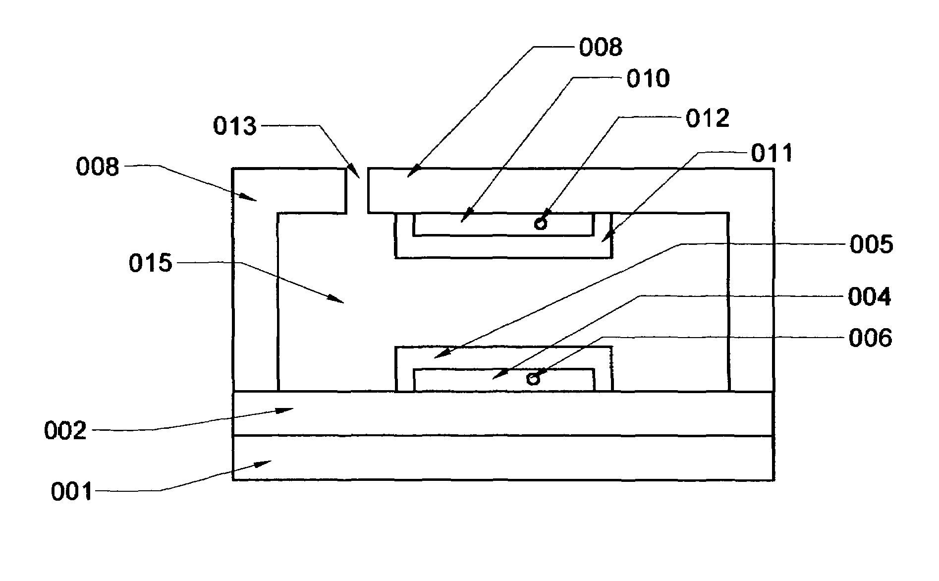
[0564]In this example, microelectromechanical systems (MEMS) technology is used in the design and fabrication of a silicon parallel-plate capacitive element that can be used as the capacitive element in certain MEMS-based embodiments of the concrete sensor of the invention. MEMS-based concrete sensors can be added into a concrete mix before the mix is placed and will record the characteristics of that mix to determine whether there are problems with alkalinity, moisture content, or other factors. After being embedded within a concrete structure, the MEMS-based sensor will continue to transmit data about the structure's maintenance requirements. The MEMS-based sensor can also withstand the weight of concrete being placed on top of it.

[0565]6.2.2 MEMS Capacitor Design

[0566]The MEMS-based parallel-plate capacitive element (“MEMS capacitor”) is approximately 3 mm2, which is fairl...


PUM


Abstract

The invention provides a sensor for monitoring an environmental parameter in concrete including an enclosure; a detecting device connected to the enclosure for a detecting at least one environmental parameter in concrete, wherein the detecting device includes at least one capacitive element; an active material connected to the enclosure, wherein the active material is liable to respond to the environmental parameter and is operably connected to the capacitive element; a RFID chip mounted within the enclosure and operably connected to the detecting device; and an antenna operably connected to the RFID chip and the detecting device, wherein the antenna is part of an L-R-C circuit whose resonance frequency shifts within an assigned frequency band. The invention also provides a MEMS-based capacitive element that responds to an environmental parameter in concrete. The invention further provides a method of forming a MEMS-based capacitive element.

Description

CROSS-REFERENCE TO RELATED APPLICATIONS[0001]This application is a continuation-in-part of pending application Ser. No. 10 / 732,717 filed December 10, 2003, which is incorporated herein by reference in its entirety.STATEMENT REGARDING FEDERALLY SPONSORED RESEARCH OR DEVELOPMENT[0002]The disclosed invention was made with government support under award No. DMI-00338986 from the National Science Foundation. The government may have rights in this invention.REFERENCE TO APPENDIX[0003]Not applicable1. TECHNICAL FIELD[0004]The present invention relates to sensors for monitoring concrete condition. The ion also relates to sensors that measure environmental parameters in concrete such as re content, temperature, pH and concentrations of ions such as chloride, sodium or potassium.2. BACKGROUND OF THE INVENTION[0005]With infrastructure costs escalating, it is becoming essential to monitor and / or evaluate the health of concrete structures so that timely maintenance can maximize their useful live...

Claims


Application Information

Patent Timeline
IPC IPC(8): G01R27/26
CPCG01N33/383G01N27/226
Inventor JOHNSON, ERIC ARTHUR
Owner ADVANCED DESIGN CONSULTING USA
Learn More