Process of forming oil-absorbent bodies

a technology of oil-absorbent bodies and oil-absorption tanks, which is applied in the direction of water/sewage treatment by substance addition, hydraulic engineering, construction, etc., can solve the problems of large annual costs both financially and physically, and the number of units of specialized equipment cannot be easily transported, so as to achieve the effect of effectively containing water-borne oil spills

Inactive Publication Date: 2006-05-23
LIGHTAIR HLDG +1
View PDF194 Cites 11 Cited by
  • Summary
  • Abstract
  • Description
  • Claims
  • Application Information

AI Technical Summary

Benefits of technology

[0015]It is another object of the invention to provide methods and apparatus for effectively containing water-borne oil spills, even under adverse conditions or near shorelines, rocks, and reefs.
[0017]It is another object of the invention to provide a means of improving the collection of spilled oil.
[0020]It is another objective of the invention to provide systems for controlling oil spills that provide for the economical recycling of the collected oil as fuel.
[0023]Thus, the inventive systems, devices, and methods can be used to permit (1) easy and quick deployment of containment equipment, even if a spill is in an inconvenient or distant location, (2) effective control of the spilled oil during any delays in recovery, and (3) comparatively inexpensive and easy collection of the oil during the clean-up stage. The system is specifically designed for rapid deployment and efficiency in rough water.

Problems solved by technology

The continuing incidence of oil spillage into both marine and inland waterways due to shipping accidents results in enormous annual costs both financially to the shipping and insurance industries and environmentally.
Many spill incidents occur in bad weather or in remote locations.
There is a limited number of units of specialized equipment, and they are not easily transported.
Thus, in many cases, response to the spill is delayed for many hours or even days.
The impact of a spill is greatly increased by both bad weather and delayed response.
An additional problem is the high cost of disposal of the recovered material.
Current recovery systems create large quantities of waste, which must be disposed of as hazardous waste at high financial cost.
Systems for applying these materials to oil spills are less developed.
Either method creates severe collection problems for sorbent material in particulate form, including sinking of the oil-loaded material, loss of the oil-loaded material due to dispersion by wave or wind action, and dissolution of the oil-sorbent material in the oil spill.
These problems are exacerbated when the spill occurs in bad weather or near shorelines.
In addition, because 90% of spilled oil is typically located in 10% of the spill area, the dissolution problem can be particularly troublesome inside barriers.
Further, the application of oil-sorbing material typically employs spill boats, which rely on availability of the boat and access to the spill.
Both of these can be a severe problem in remote locations or bad weather.
However, these containers have a tendency to pile up on top of each other, creating an undesirable condition in which a significant amount of the sorbent material is either below the waterline or floating above the oil, in either case out of contact with the oil.
In addition, the large cross section of these types of containers tends to result in an “oil lock-out” phenomenon, in which the surface of the material becomes saturated with oil, effectively preventing oil migration to the center of the material.
However, oil-sorbent booms are not designed to sorb substantial amounts of oil, but rather are generally used to retrieve a sheen or a small oil spill or to prevent the spill from expanding or reaching a protected area such as a shoreline until it can be collected by mechanical means, typically utilizing skimmers or oil-recovery boats.
Containment systems employing traditional booms have numerous problems.
Deployment of some booms requires specialized equipment, which can be slow and difficult.
If the spill is large, surrounding the spill may not be possible due to lack of sufficient boom resources.
All of these problems can delay response to the spill.
Therefore, boom and skimmer systems do not work well in rough water or near obstacles.
Delayed response to a spill results in a number of deleterious changes.
A spill spreads uncontrollably and rapidly to a thin layer on water (less than 1 mm in many cases), making containment extremely difficult if not impossible.
If close to shore, the oil may wash ashore, causing severe environmental damage.
Lighter fractions of the oil (volatile organic compounds) are released into the atmosphere, resulting in hydrocarbon air pollution.
The oil will undergo aging and emulsification, which can cause the oil to sink, making cleanup even more difficult.
All of these changes cause the cleanup of the spill to become much more difficult, increase the environmental impact, and raise the financial cost of the cleanup.

Method used


Image

  • Process of forming oil-absorbent bodies
  • Process of forming oil-absorbent bodies
  • Process of forming oil-absorbent bodies

Examples


Embodiment Construction

[0042]The system includes the application to the oil spill of hundreds or thousands of sacks containing a quantity of appropriately formed bodies comprising copolymer-based materials that are known to absorb and entrap crude or refined hydrocarbon products, including crude oil of any viscosity and gasoline or other refined fuels. For purposes of this application, the term “oil” refers to any hydrocarbon material.

Sack Deployment

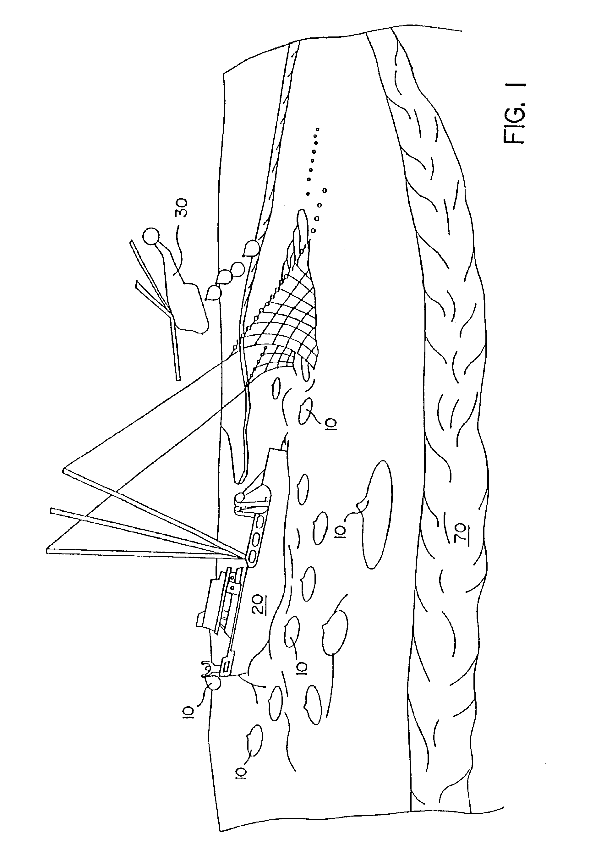
[0043]FIG. 1 illustrates an oil spill and certain deployment and retrieval activities in accordance with the invention, including a plurality of the inventive containers, referenced as sacks 10. To simplify the application, a number of different activities are shown in FIG. 1, although in practice, many of those activities may take place at different times or in different locations. In FIG. 1, a number of sacks 10 are shown being applied to an oil spill. The containers are designed for easy application from floating platforms or ships, as shown at the left of ...


PUM

PropertyMeasurementUnit
temperatureaaaaaaaaaa
heightaaaaaaaaaa

Abstract

A process for forming an oil-sorbent composition of matter with bound combinations of styrene-butadiene-styrene (SBS) and ethylene propylene diene monomer (EPDM) utilizes a low-temperature extrusion process. The SBS, or both materials, may be in the form of multitudes of granules. In certain preferred embodiments, the combination is 10-30% by weight and the SBS is about 30% styrene and manufactured without talc. The composition of matter can be extruded into a solid, compliant body for use in a product for absorbing oil. The material can be extruded, in one preferred embodiment, into an extended cylinder body having an axial hole.

Description

CROSS-REFERENCED RELATED APPLICATIONS[0001]This application is a division of application Ser. No. 10 / 038,461, filed Dec. 31, 2001, now U.S. Pat. No. 6,723,791, which is a continuation of application Ser. No. 09 / 005,332, filed Jan. 9, 1998, now U.S. Pat. No. 6,344,519, which claims the benefit of U.S. Provisional Application No. 60 / 034,677, filed Jan. 10. 1997.FIELD OF THE INVENTION[0002]This invention is in the field of systems and methods for recovering hydrocarbons from water, including oil spills on open-water surfaces such as the ocean.BACKGROUND OF THE INVENTION[0003]The continuing incidence of oil spillage into both marine and inland waterways due to shipping accidents results in enormous annual costs both financially to the shipping and insurance industries and environmentally. Many spill incidents occur in bad weather or in remote locations. Current systems for ameliorating oil spills require that specialized spill-response ships containing unique heavy equipment reach the s...

Claims


Application Information

Patent Timeline
Patent Type & Authority Patents(United States)
IPC IPC(8): B29C67/20B01D15/00E02B15/10B01D17/02B01J20/26C02F1/40C02F1/68C08L9/00C08L23/16C08L51/00C08L53/00C08L53/02C09K3/32E02B15/04
CPCB01D17/0202B01J20/261C02F1/681C08L23/16C08L51/006C08L53/00C08L53/02C09K3/32E02B15/041B01J20/26B01D17/0214Y10S210/925C02F2101/32Y10S210/924Y10S210/923Y10S588/90Y10S588/901C08L2666/24C08L2666/04C08L2666/02Y02A20/204B01D15/00E02B15/10C08L9/00
Inventor RINK, GLENN R.MORRIS, JAMES F.STELPSTRA, STEPHEN C.
Owner LIGHTAIR HLDG
Why Eureka
Try Eureka