Method for producing metal laminate

a metal laminate and metal technology, applied in the field of metal laminate production, can solve the problems of thermal strain on the film by tension, insufficient elimination of residual strain, etc., and achieve the effect of effective elimination of residual strain of the film and excellent dimension stability

Inactive Publication Date: 2006-05-30
KURARAY CO LTD
View PDF18 Cites 6 Cited by
  • Summary
  • Abstract
  • Description
  • Claims
  • Application Information

AI Technical Summary

Benefits of technology

[0018]In the method of the present invention, the metal sheet is preferable to be thermally press-bonded to at least one side of the thermoplastic liquid crystal polymer film continuously. Also, a height of the unevenness provided on the surface of the heat treatment roll is preferably 1 to 15 μm in order to effectively eliminate the residual strain of the film. Further, a temperature of the hea...

Problems solved by technology

This does not sufficiently eliminate the residual stra...

Method used


Image

  • Method for producing metal laminate
  • Method for producing metal laminate
  • Method for producing metal laminate

Examples


reference example 1

[0070]A thermoplastic liquid crystal polymer, which is a copolymer of p-hydroxybenzoic acid and 6-hydroxy-2-naphthoic acid and having a melting point of 280° C., was melt-extruded at an output rate of 20 Kg / hour to give a film by the inflation molding method under conditions that lateral expansion rate was 4.00 times and vertical expansion rate was 2.50 times. As a result, the thermoplastic liquid crystal polymer film having average thickness of 50 μm, thickness distribution of ±7% and MD to TD ratio of tensile strength of 1.05 was obtained. The thermal dimensional change at 200° C. of the film was +0.1% in the MD direction and −0.5% in the TD direction. Also, the thermal deflection temperature was 200° C. This thermoplastic liquid crystal polymer film is referred to as A-type.

reference example 2

[0071]A thermoplastic liquid crystal polymer, which is a copolymer of p-hydroxybenzoic acid and 6-hydroxy-2-naphthoic acid and having a melting point of 280° C., was melt-extruded at an output rate of 20 Kg / hour to give a film by the inflation molding method under conditions that lateral expansion rate was 2.00 times and vertical expansion rate was 5.00 times. As a result, the thermoplastic liquid crystal polymer film having average thickness of 50 μm, thickness distribution of ±7% and MD to TD ratio of tensile strength of 3.5 was obtained. The thermal dimensional change at 200° C. of the film was +0.8% in the MD direction and −2.0% in the TD direction. Also the thermal deflection temperature was 200° C. This thermoplastic liquid crystal polymer film is referred to as B-type.

example 1

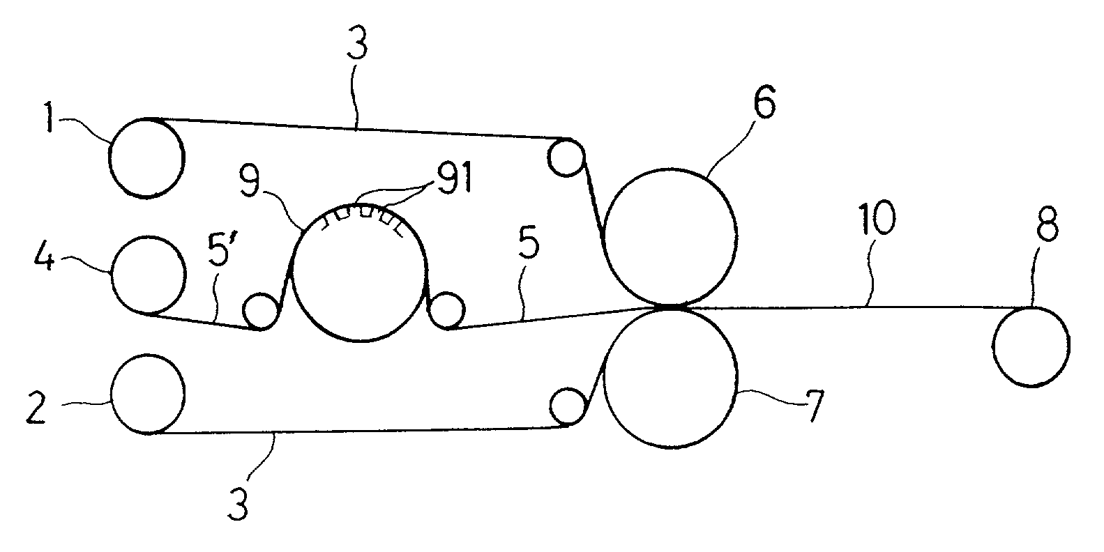
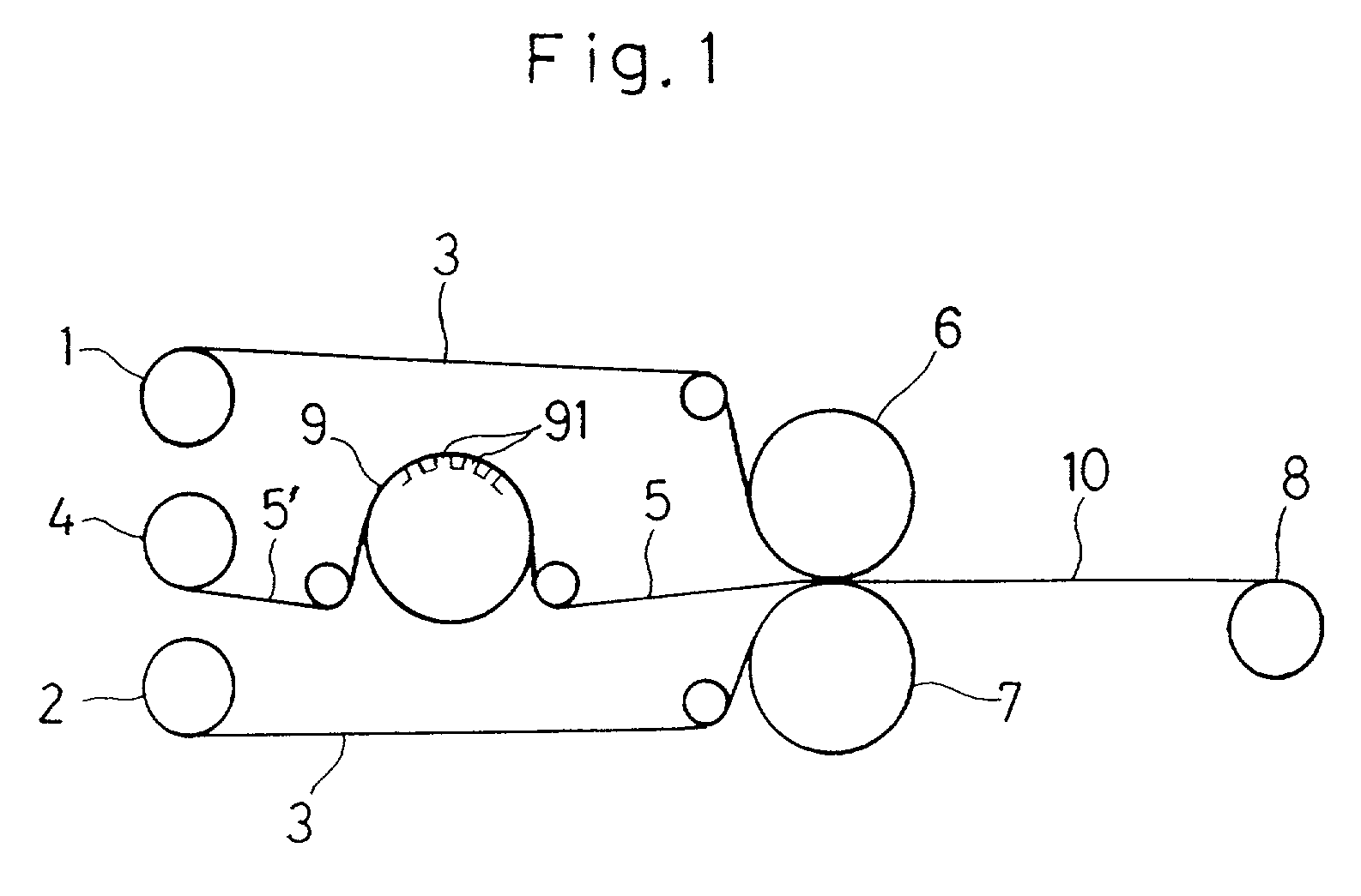
[0072]The thermoplastic liquid crystal polymer film of A-type obtained in the Reference Example 1 and electrolytic copper foils having a thickness of 18 μm were used. A roll having a lot of unevenness 91 with a height of 15 μm at a rate of 10 per 10000 μm2 on its surface was attached as the heat treatment roll 9 to the continuous hot roll press apparatus shown in FIG. 1. A temperature of the heat treatment roll 9 was set to 200° C. and a temperature of the press rolls 6 and 7 was set to 260° C. The film of A-type and the electrolytic copper foils were thermally press-bonded by these rolls at a pressure of 10 Kg / cm2, while being drawn at a rate of 2 m / min, to give a double-sided metal laminate 10 having a structure of metal foil / thermoplastic liquid crystal polymer film / metal foil structure. A tension of 3 Kg / 40 cm width was applied to the thermoplastic liquid crystal polymer film 5′. Also, the time for which the thermoplastic liquid crystal polymer film 5′ contacts with the heat tre...


PUM

PropertyMeasurementUnit
Temperatureaaaaaaaaaa
Lengthaaaaaaaaaa
Lengthaaaaaaaaaa

Abstract

To continuously produce a metal laminate having excellent dimensional stability and flatness, there is provided with a method of producing a metal laminate in which a thermoplastic liquid crystal polymer film (5′) capable of forming an optically anisotropic melt phase is heat-treated on a heat treatment roll having unevenness (91) on its surface and subsequently a metal sheet (3) is bonded to at least one side of the film (5′).

Description

BACKGROUND OF THE INVENTION[0001]1. Field of the Invention[0002]The present invention relates to a method for producing a metal laminate having a film (which film is hereinafter referred to as a thermoplastic liquid crystal polymer film) made of a thermoplastic polymer capable of forming an optically anisotropic melt phase (which thermoplastic polymer is hereinafter referred to as a thermoplastic liquid crystal polymer). The metal laminate obtained by the method of this invention has excellent properties such as low moisture absorbability, heat resistance, chemical resistance and electrical properties deriving from the thermoplastic liquid crystal polymer film and also has excellent thermal dimensional stability. Therefore, it is useful as a material for a circuit board or a base material which requires thermal dimensional stability.[0003]2. Description of the Related Art[0004]In recent years, the demands for scale reduction and weight reduction in portable electronic devices for mo...

Claims


Application Information

Patent Timeline
IPC IPC(8): B32B37/00B32B15/08B32B38/04B32B38/06H05K3/02
CPCB32B15/08B32B38/06H05K3/022B32B2311/00B32B2457/08B32B2305/55
Inventor ONODERA, MINORUSUNAMOTO, TATYUYAYOSHIKAWA, TADAO
Owner KURARAY CO LTD
Why Eureka
Try Eureka