Methods of determining concentration of glucose

a glucose concentration and glucose technology, applied in the field of analytical sensors, can solve the problems of inconvenient procedure, inability to accurately and efficiently measure a bioanalyte, and type of inaccuracy, so as to reduce the volume of the chamber, accurately and efficiently measure a bioanalyte, and reduce the volume of the sampl

Inactive Publication Date: 2006-06-06
ABBOTT DIABETES CARE INC
View PDF357 Cites 462 Cited by
  • Summary
  • Abstract
  • Description
  • Claims
  • Application Information

AI Technical Summary

Benefits of technology

[0009]In a preferred embodiment, the working electrode faces a counter electrode, forming a measurement zone within the sample chamber, between the two electrodes, that is sized to contain no more than about 1 μL of sample, preferably no more than about 0.5 μL, more preferably no more than about 0.25 μL, and most preferably no more than about 0.1 μL of sample. A sorbent material is optionally positioned in the sample chamber and measurement zone to reduce the volume of sample needed to fill the sample chamber and measurement zone.
[0010]In one embodiment of the invention, a biosensor is provided which combines coulometric electrochemical sensing with a non-leachable or diffusible redox mediator to accurately and efficiently measure a bioanalyte in a submicroliter volume of sample. The preferred sensor includes an electrode, a non-leachable or diffusible redox mediator on the electrode, a sample chamber for holding the sample in electrical contact with the electrode and, preferably, sorbent material disposed within the sample chamber to reduce the volume of the chamber. The sample chamber, together with any sorbent material, is sized to provide for analysis of a sample volume that is typically no more than about 1 μL, preferably no more than about 0.5 μL, more preferably no more than about 0.25 μL, and most preferably no more than about 0.1 μL. In some instances, the sensor also contains a non-leachable or diffusible second electron transfer agent.
[0013]One aspect of the invention is a method of determining the concentration of an analyte in a sample by contacting the sample with an electrochemical sensor and determining the concentration of the analyte by coulometry. The electrochemical sensor includes an electrode pair with a working electrode and a counter electrode. The sensor also includes a sample chamber for holding a sample in electrolytic contact with the working electrode. Within the sample chamber is sorbent material to reduce the volume sample needed to fill the sample chamber so that the sample chamber is sized to contain no more than about 1 μL of sample. The sample chamber also contains a non-leachable or diffusible redox mediator and optionally contains a non-leachable or diffusible second electron transfer agent.
[0014]The sensors may also include a fill indicator, such as an indicator electrode or a second electrode pair, that can be used to determine when the measurement zone or sample chamber has been filled. An indicator electrode or a second electrode pair may also be used to increase accuracy of the measurement of analyte concentration. The sensors may also include a heating element to heat the measurement zone or sample chamber to increase the rate of oxidation or reduction of the analyte.

Problems solved by technology

These procedures are inconvenient for the patient, and often painful, particularly when frequent samples are required.
However, lancing the body in the preferred regions typically produces submicroliter samples of blood, because these regions are not heavily supplied with near-surface capillary vessels.
However, the use of an electrochemical sensor for measuring analyte in a small volume introduces error into the measurements.
One type of inaccuracy arises from the use of a diffusible redox mediator.
Another source of inaccuracy in a small volume sensor is the difficulty in determining the volume of the small sample or in determining whether the sample chamber is filled.

Method used


Image

  • Methods of determining concentration of glucose
  • Methods of determining concentration of glucose
  • Methods of determining concentration of glucose

Examples


example 1

Preparation of a Small Volume in Vitro Sensor for the Determination of Glucose Concentration

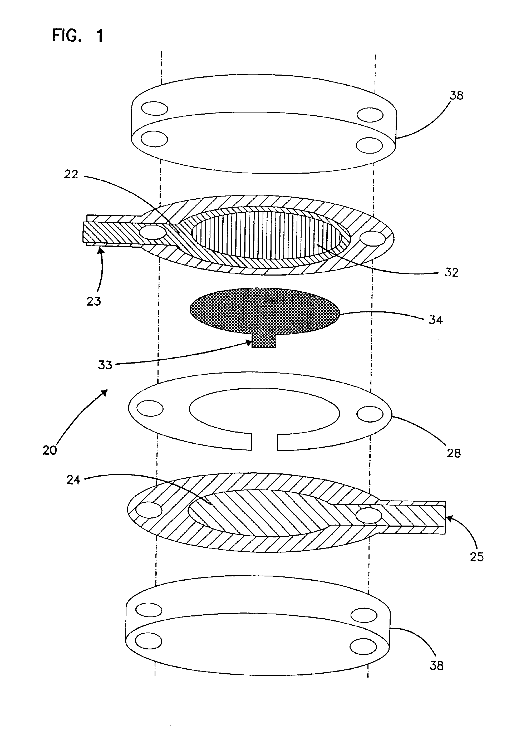
[0305]A sensor was constructed corresponding to the embodiment of the invention depicted in FIG. 1. The working electrode was constructed on a Mylar™ film (DuPont), the Mylar™ film having a thickness of 0.175 mm and a diameter of about 2.5 cm. An approximately 12 micron thick carbon pad having a diameter of about 1 cm was screen printed on the Mylar™ film. The carbon electrode was overlaid with a water-insoluble dielectric insulator (Insulayer) having a thickness of 12 μm, and a 4 mm diameter opening in the center.

[0306]The center of the carbon electrode, which was not covered by the dielectric, was coated with a non-leachable redox mediator. The redox mediator was formed by complexing poly(1-vinyl imidazole) with Os(4,4′-dimethoxy-2,2′-bipyridine)2Cl2 followed by cross-linking glucose oxidase with the osmium polymer using polyethylene glycol diglycidyl ether (PEGDGE) as described in Taylor e...

example 2

Response of the Glucose Sensor to Interferents

[0320]A sensor constructed in the same manner as described above for Example 1 was used to determine the sensor's response to interferents. The primary electrochemical interferents for blood glucose measurements are ascorbate, acetaminophen, and urate. The normal physiological or therapeutic (in the case of acetaminophen) concentration ranges of these common interferents are:[0321]ascorbate: 0.034-0.114 mM[0322]acetaminophen: 0.066-0.200 mM[0323]urate (adult male): 0.27-0.47 mM

Tietz, in: Textbook of Clinical Chemistry, C. A. Burtis and E. R. Ashwood, eds., W. B. Saunders Co., Philadelphia 1994, pp. 2210-12.

[0324]Buffered glucose-free interferent solutions were tested with concentrations of the interferents at the high end of the physiological or therapeutic ranges listed above. The injected sample volume in each case was 0.5 μL. A potential of +100 mV or +200 mV was applied between the electrodes. The average charge (Qavg) was calculated...

example 3

Sensor with Glucose Dehydrogenase

[0327]A sensor similar to that described for Example 1 was prepared and used for this example, except that glucose oxidase was replaced by pyrroloquinoline quinone glucose dehydrogenase and a potential of only +100 mV was applied as opposed to the +200 mV potential in Example 1. The results are presented in Table 3 below and graphed in FIG. 10.

[0328]

TABLE 3Sensor Results Using Glucose DehydrogenasenQavg (μC)90% rise time (s)buffer421.7 ± 5.214 ± 3 3 mM glucose / buffer4 96.9 ± 15.024 ± 6 6 mM glucose / buffer4190.6 ± 18.426 ± 610 mM glucose / buffer4327.8 ± 69.342 ± 9

[0329]The results indicated that the charge obtained from the glucose dehydrogenase sensor was much larger than for the comparable glucose oxidase sensor, especially for low concentrations of glucose. For 4 mM glucose concentrations the measurements obtained by the two sensors differed by a factor of five. In addition, the glucose dehydrogenase sensor operated at a lower potential, thereby red...


PUM


Abstract

A region of skin, other than the fingertips, is stimulated. After stimulation, an opening is created in the skin (e.g., by lancing the skin) to cause a flow of body fluid from the region. At least a portion of this body fluid is transported to a testing device where the concentration of analyte (e.g., glucose) in the body fluid is then determined. It is found that the stimulation of the skin provides results that are generally closer to the results of measurements from the fingertips, the traditional site for obtaining body fluid for analyte testing.

Description

[0001]This application is a continuation of application Ser. No. 09 / 604,614, filed Jun. 27, 2000, now U.S. Pat. No. 6,591,125, which application(s) are incorporated herein by reference.FIELD OF THE INVENTION[0002]This invention relates to methods of using analytical sensors for the detection of bioanalytes.BACKGROUND OF THE INVENTION[0003]Analytical sensors are useful in chemistry and medicine to determine the presence and concentration of a biological analyte. Such sensors are needed, for example, to monitor glucose in diabetic patients and lactate during critical care events.[0004]Currently available technology measures bioanalytes in relatively large sample volumes, e.g., generally requiring 3 microliters or more of blood or other biological fluid. These fluid samples are obtained from a patient, for example, using a needle and syringe, or by lancing a portion of the skin such as the fingertip and “milking” the area to obtain a useful sample volume. These procedures are inconveni...

Claims


Application Information

Patent Timeline
Patent Type & Authority Patents(United States)
IPC IPC(8): A61B5/05A61B5/00A61B5/15
CPCA61B5/1411A61B5/1468A61B5/14532A61B2562/0295A61B5/150412A61B5/14546A61B5/150022A61B5/150358A61B5/150442A61B5/150503A61B5/15144A61B5/15194C12Q1/006G01N27/3272G01N33/48707G01N33/49G01N33/66
Inventor BUSE, JOHN BERNARDMOSES, ALAN CHARLES
Owner ABBOTT DIABETES CARE INC
Why Eureka
Try Eureka