
Global closed loop control system with dv/dt control and EMI/switching loss reduction

a closed loop control and control system technology, applied in the direction of dynamo-electric converter control, pulse technique, instruments, etc., to achieve the effect of improving the reduction of differential mode noise, improving the reduction of common mode noise, and fast measuremen

Active Publication Date: 2006-06-13
INFINEON TECH AMERICAS CORP
View PDF8 Cites 49 Cited by
  • Summary
  • Abstract
  • Description
  • Claims
  • Application Information

AI Technical Summary

Benefits of technology

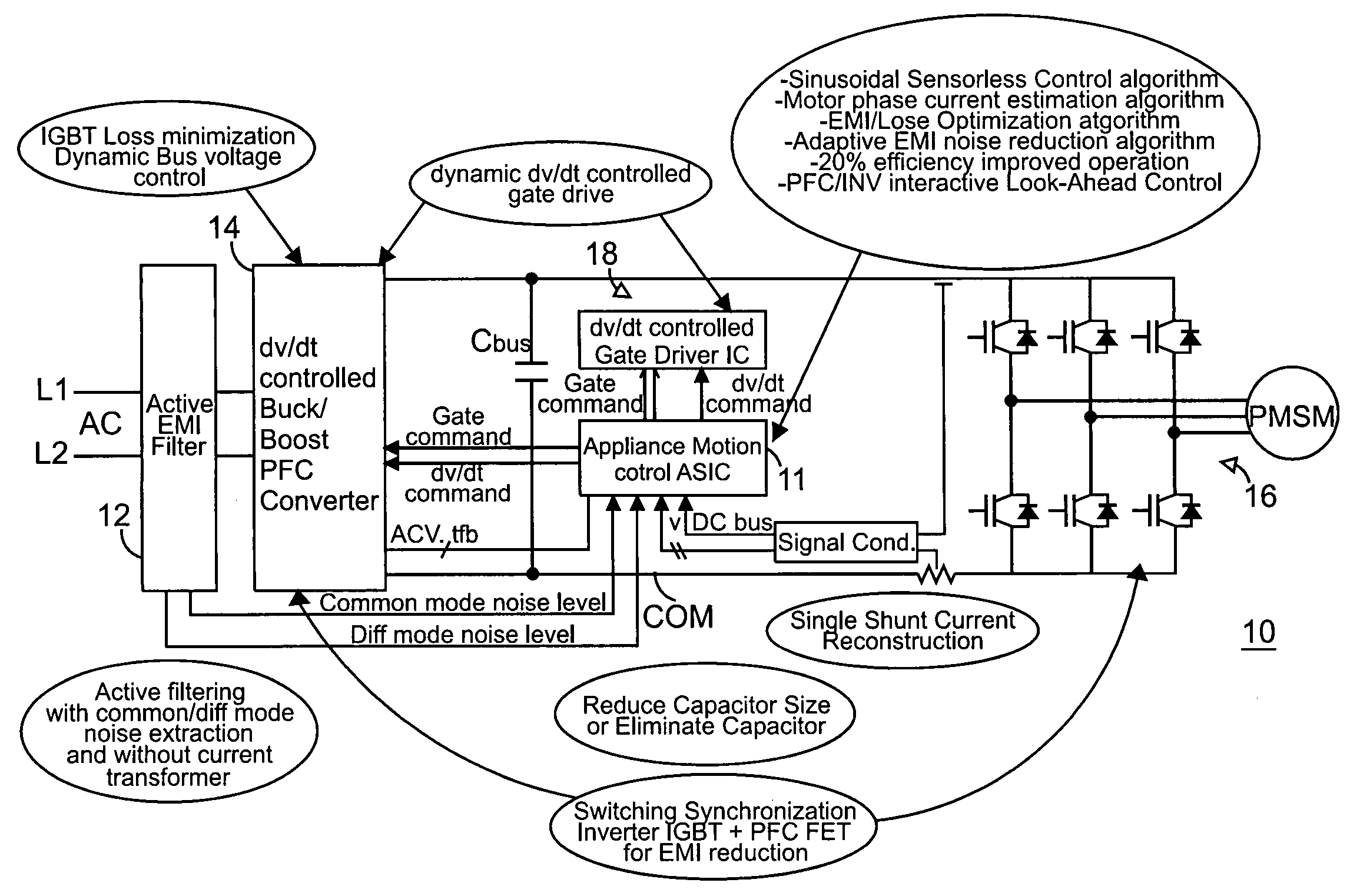
The present invention provides a closed loop control system for global synchronous motor control and synchronized switching to reduce EMI production. The system uses dynamic bus voltage control and dynamic dv / dt control for inverter gate drives. The control system offers power factor correction control through a dynamic switching scheme to permit zero voltage switching with minimal current. Active EMI filtering provides a reduction in common mode and differential mode noise in the system. The control system obtains an estimation of motor current by measuring only the de bus voltage provided to the inverter. Algorithms for synchronizing switching between the inverter and the power factor correction circuit, as well as adaptive EMI noise reduction, increase the efficiency of the overall system and produce a more reliable and cost effective overall motor drive system solution. The control system provides an interactive look ahead control scheme to coordinate the power factor correction and inverter operation for improved operational reliability and efficiency. The control system offers control for a voltage rate of change per unit time in turning on or turning off the power switches of the power converter or power inverter of the motor drive system. The control system can quickly measure noise signals and use the information to cancel noise in the system or change the operating points of various components to reduce generated noise.

Problems solved by technology

There is a tradeoff between EMI noise reduction through control of the change in voltage per unit time applied to the gate of the power switches, and switching losses in the power switches.

Method used


Image

  • Global closed loop control system with dv/dt control and EMI/switching loss reduction
  • Global closed loop control system with dv/dt control and EMI/switching loss reduction
  • Global closed loop control system with dv/dt control and EMI/switching loss reduction

Examples


Embodiment Construction

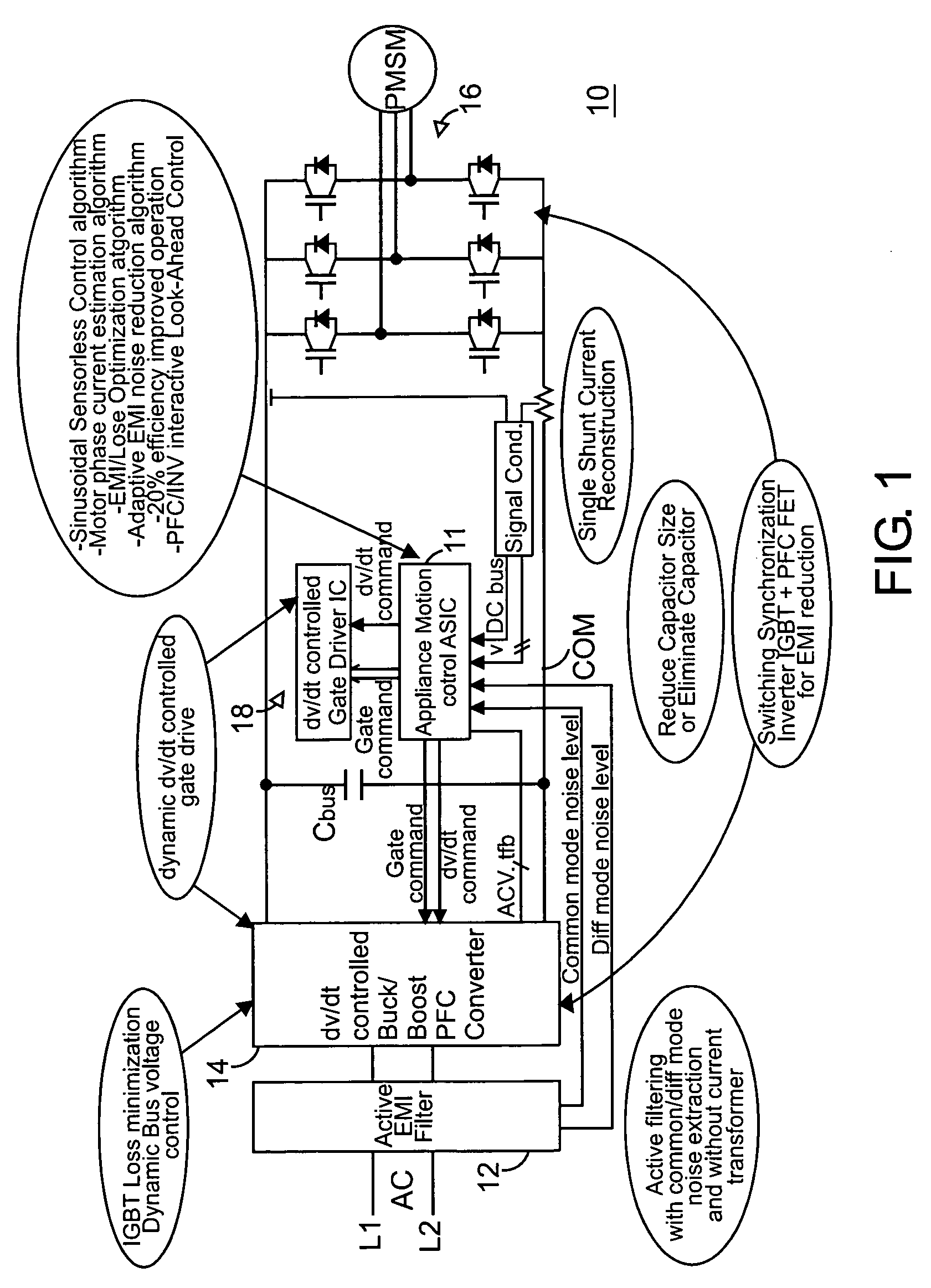
[0045]Referring now to FIG. 1, an overall global closed loop motor control system is illustrated generally as system 10. System 10 includes several major subsystems including an active EMI filter 12, a power factor correction and power converter circuit 14, and an inverter circuit 16 and an inverter control 18. A global system control 11 provides the overall command, control and feedback circuitry and computation for operating drive system 10.

[0046]Active EMI filter 12 senses common and differential mode noise on input a-c lines L1, L2 and optionally on a common line COM, and provides a feedback signal to cancel the noise generated in system 10. A detailed discussion of active EMI filter 12, showing various embodiments with circuit diagrams is provided in U.S. Pat. No. 6,775,157, issued Aug. 10, 2004, the entire contents of which is hereby incorporated by reference in the present application. Active EMI filter 12 provides excellent noise reduction operation to greatly improve overal...


PUM


Abstract

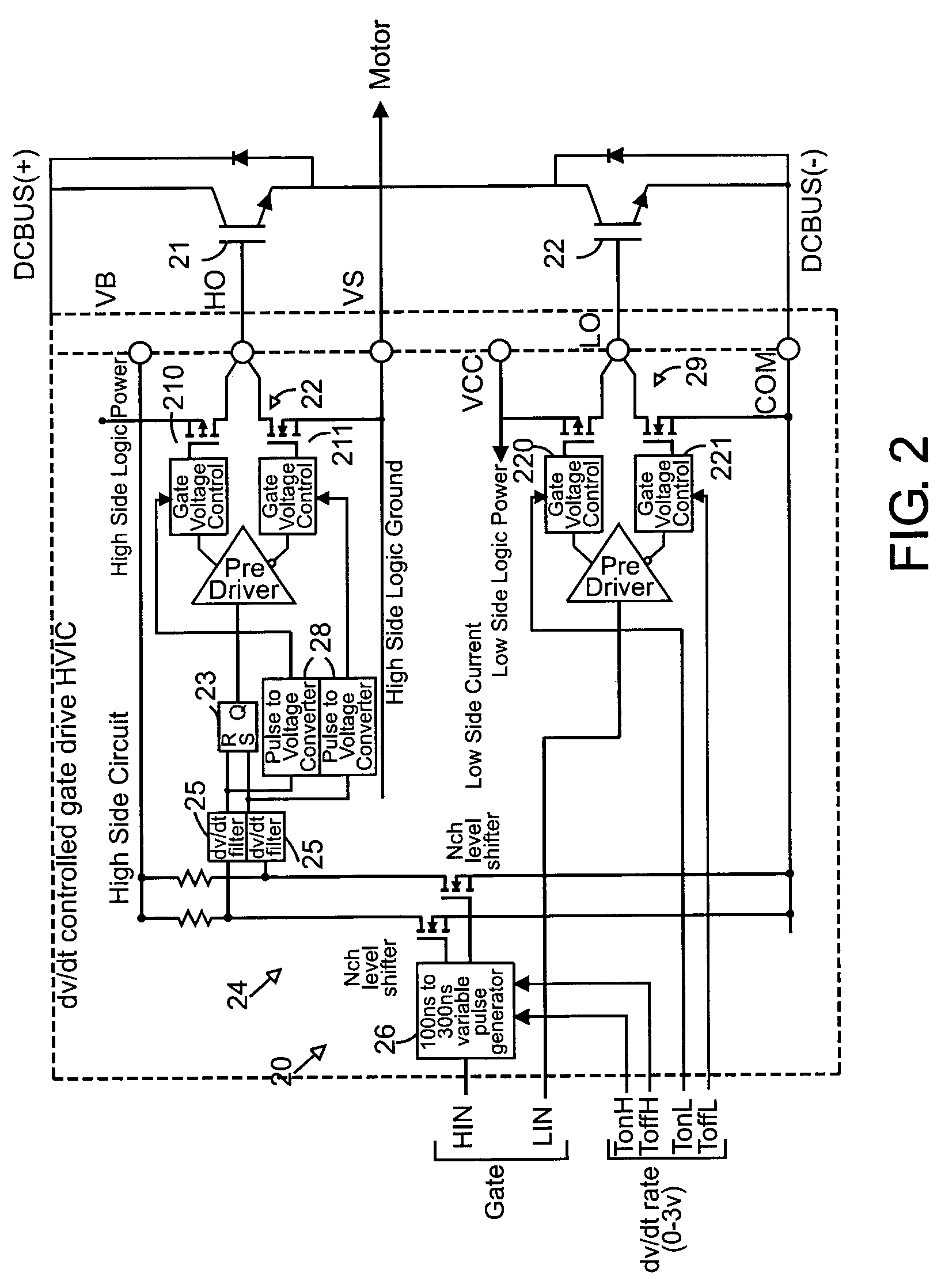
A motor drive system control provides global closed loop feedback to cooperatively operate system components to adaptively reduce noise and provide noise cancellation feedback. An active EMI filter reduces differential and common mode noise on an input and provides a noise level indication to a system controller. Power switches in both a power converter and power inverter are cooperatively controlled with dynamic dv / dt control to reduce switching noise according to a profile specified by the controller. The dv / dt control is provided as an analog signal to a high voltage IC and codified as a pulse width for a level shifting circuit supplying control signals to the high voltage gate drive. A noise extraction circuit and technique obtain fast noise sampling to permit noise cancellation and adaptive noise reduction.

Description

RELATED APPLICATIONS[0001]This application is based on and claims benefit of U.S. Provisional Application Ser. No. 60 / 399,368, filed Jul. 25, 2002, entitled EMI / LOSS OPTIMIZATION SYSTEM WITH GLOBAL CLOSED LOOP CONTROL, and is based on and claims benefit of U.S. Provisional Application Ser. No. 60 / 398,621, filed Jul. 25, 2002, entitled DV / DT CONTROLLED GATE DRIVE HVIC, a claim of priority being hereby made to all of the above provisional applications.BACKGROUND OF THE INVENTION[0002]1. Field of the Invention[0003]The present invention relates generally to closed loop power control systems, and relates more particularly to closed loop power control systems with reduced EMI and switching losses and control of the rate of change of gate drive signals.[0004]2. Description of Related Art[0005]High-speed switching devices such as bipolar transistors, MOSFETs and IGBT's enable increased carrier frequency for voltage-source PWM inverters, thus leading to much better operating characteristics...

Claims


Application Information

Patent Timeline
Patent Type & Authority Patents(United States)
IPC IPC(8): G05B5/01G05F1/70H02M1/08H02M1/44H02M5/458H02P27/06H03K17/16
CPCH02M1/44H02M5/458H03K17/168H03K17/163H02M1/0029H02M1/123H02M7/48H02M1/12H02M7/5387
Inventor HO, EDDY YING YINLI, YONGHONDA, JUNTAM, DAVID C.TAKAHASHI, TOSHIO
Owner INFINEON TECH AMERICAS CORP
Learn More