This helps you quickly interpret patents by identifying the three key elements:
Problems solved by technology
Method used
Benefits of technology
[0026]Range resolution in the present invention is provided by using a telescope-fiber optic transmission/collection system. A telescope having an effective aperture (the aperture equal to the beam diameter of the optical beam emerging from the telescope) large enough at the operating wavelength is used so that the air data, wind shear, or object ranges of interest are well within the far field limit of the telescope. By using such apertures, the process of focusing of the transmitted optical beam at a particular distance (the desired range) when combined with collection of the scattered radiation by the same telescope and focusing of the collected radiation into a single mode optical fiber produces automatic range resolution. Only those aerosols or objects within the depth of field of the telescope focus will scatter energy that can be efficiently collected by the telescope-fiber optic collection system. The result is a system that is largely immune to the effects of vibr
Problems solved by technology
These systems were large and weighed hundreds of pounds.
The telescope focuses the beam to strike an object or airborne particulates at a point of interest, resulting in a scattered beam.
The source of the reference beam is often a major problem in this type of system.
However, over the transit time of the launched beam, the two beams can become decorrelated, which can result in significant measurement error.
Another major limitation in the use and application of laser systems to the measurement of wind shear or air speed or objects such as automobiles or baseballs or other objects has been the lack of an eye-safe source of radiation with sufficient energy.
YAG and CO2 lasers do not operate in this wavelength range, and thus the power levels and energy per pulse levels necessary for
Method used
Image
Click on the blue label to locate the original text in one second.
Reading with bidirectional positioning of images and text.
Examples
Embodiment Construction
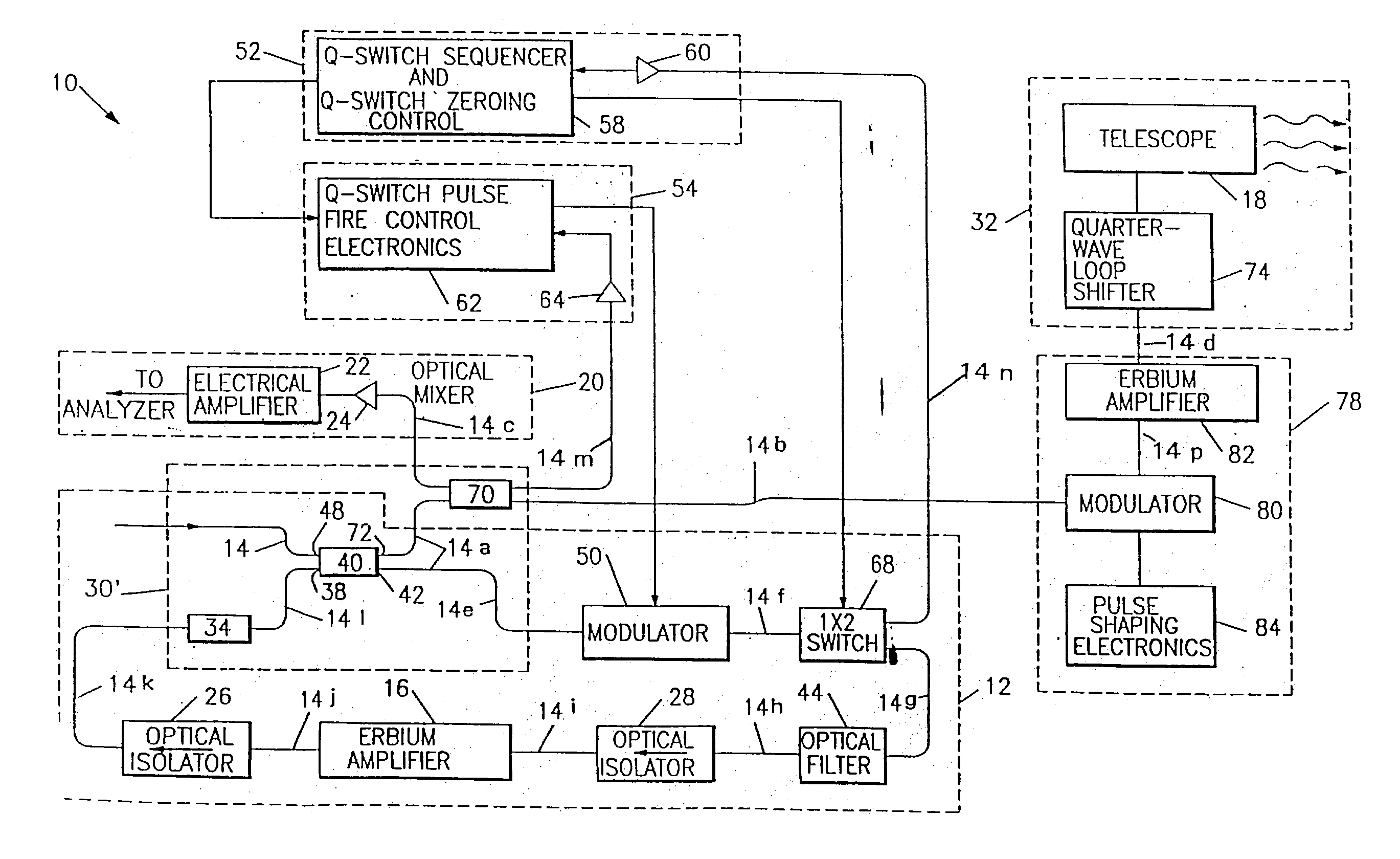
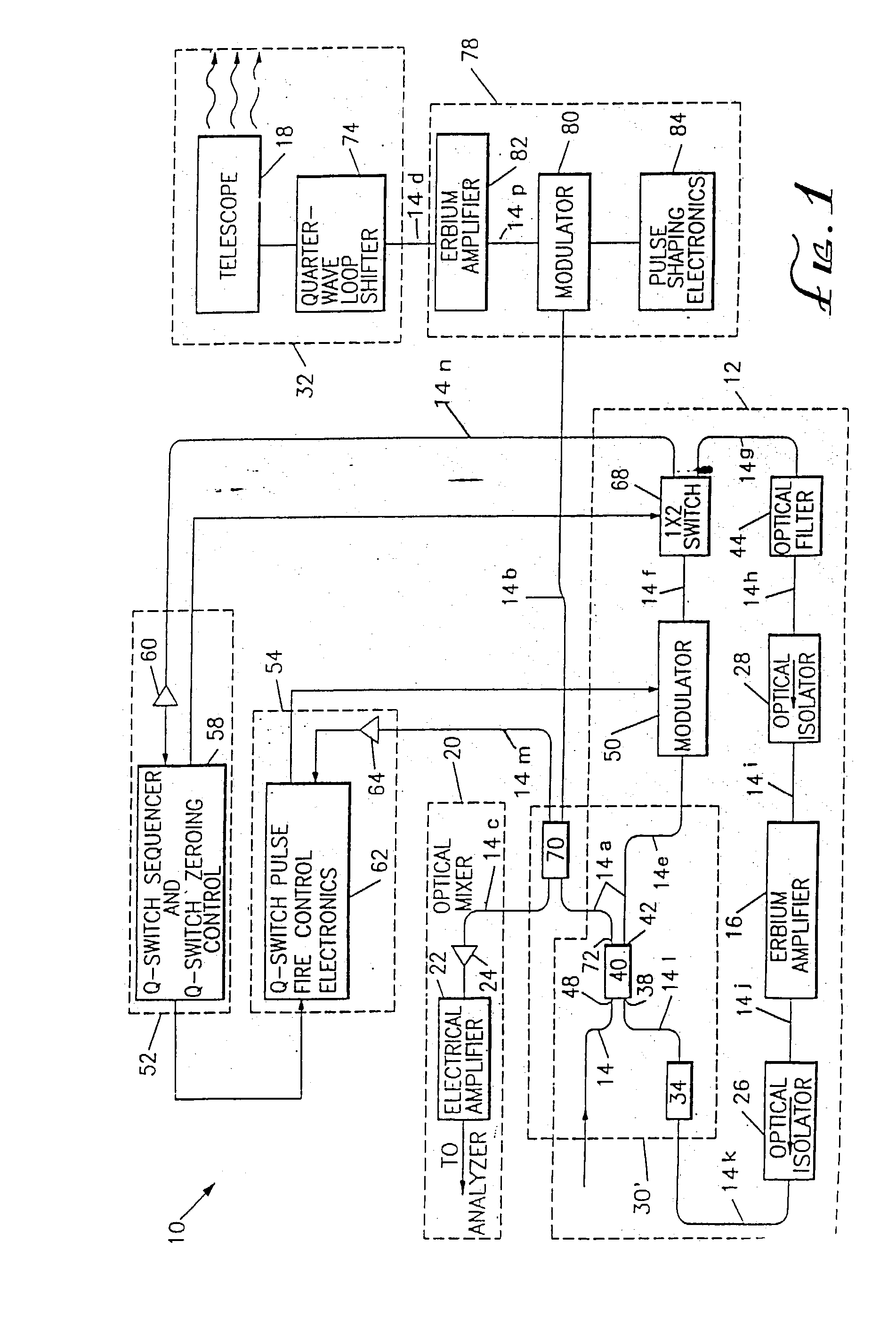
[0035]According to the present invention a laser Doppler velocimeter 10 is formed from the subsystems depicted in FIG. 1. The components used in this system are commercially available or are available as custom components from various manufacturers. The laser Doppler velocimeter can be configured to operate in four distinct modes. Three of these modes take advantage of the energy storage properties of erbium-doped optical fiber in a different way to produce a high energy coherent pulse of energy using low power commercial laser diode pump sources. A fourth mode operates ring or linear geometry laser devices in a continuous fashion, but at high power through use of very high power laser pump diodes.
Operational Mode I:
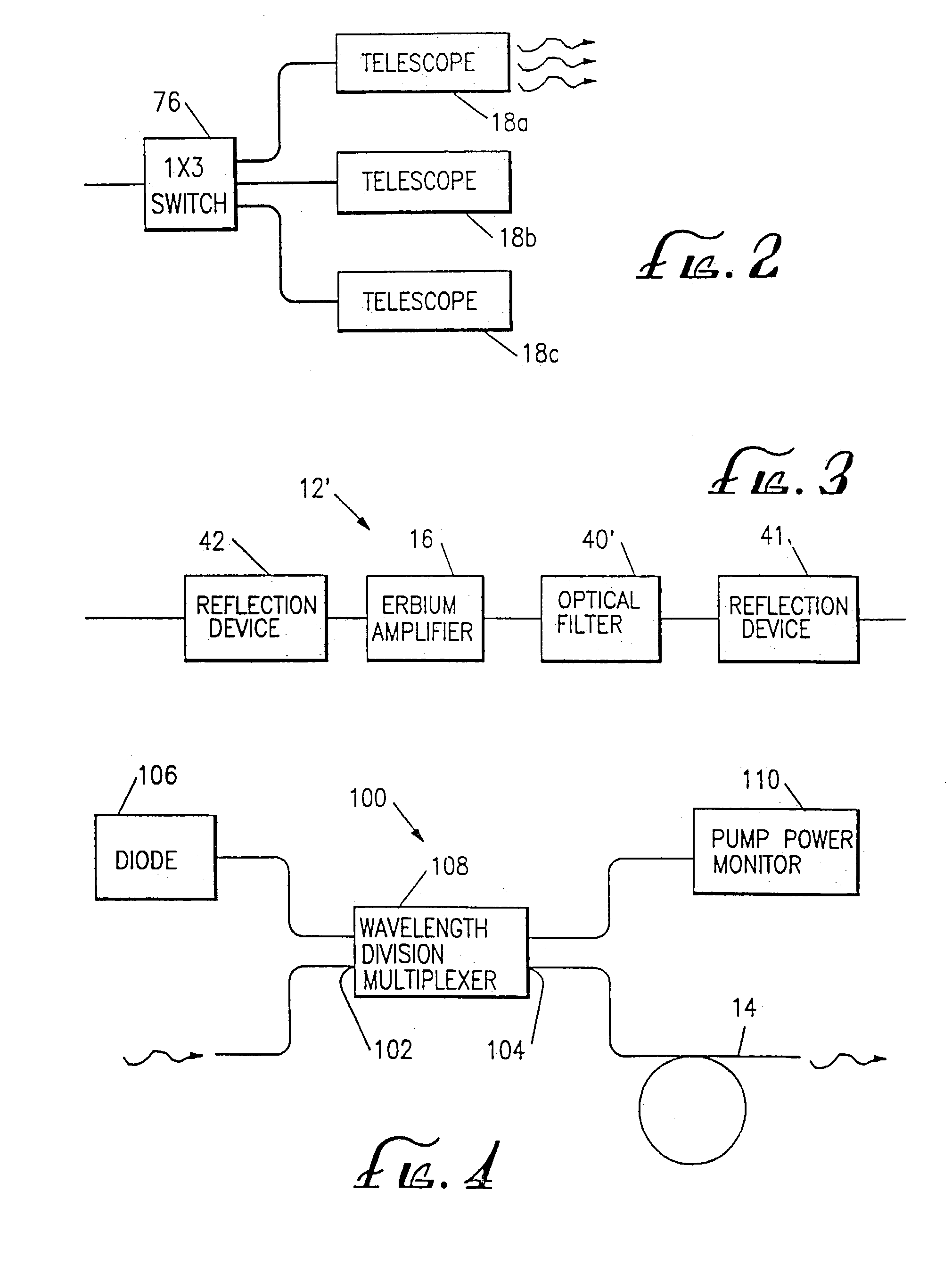
[0036]The laser Doppler velocimeter 10 includes a laser 12 formed in a ring geometry as indicated by dashed lines in FIG. 1 or a laser 12′ formed in a linear or Fabry-Perot geometry as shown in FIG. 3. The laser subsystem uses an optical wave guide formed from optical fi...
PUM
Abstract
A laser Doppler velocimeter is formed using erbium-doped fiber as the lasing medium. The fiber is diode-pumped. By properly modulating the lasing in the fiber, pulses of radiation may be generated. A telescope acts as the transmission device to focus the radiation at a specified point, and may also act as the receiving system for reflected radiation. The portion of the reflected radiation collected by the receiving system is analyzed to determine the Doppler shift caused by aerosols or objects at the focal point of the telescope.
Description
RELATED APPLICATION[0001]This application is a continuation of U.S. Ser. No. 09 / 702,132, filed Oct. 31, 2000 now abandoned, which is a continuation of Ser. No. 80 / 169,129, filed Dec. 20, 1993, now U.S. Pat. No. 6,141,086, which is a continuation in part of Ser. No. 07 / 804,888, filed Dec. 6, 1991, now U.S. Pat. No. 5,272,513.BACKGROUND OF THE INVENTION[0002]This invention relates to laser doppler velocimeters and in particular to a laser doppler velocimeter for measuring the velocity of objects or wind such as to ascertain the speed or relative speed of the object such as an automobile or in the case of wind measurement, the true air speed or wind gradients such as wind shear and having reduced cost and weight and increased eye safety.[0003]Laser doppler velocimetry (LDV) in gases at long ranges has been a subject of investigation for nearly 20 years. For instance, U.S. Pat. No. 3,915,572, issued Oct. 28, 1975, discloses a laser Doppler velocimeter. The basic LDV process compares a r...
Claims
Application Information
Patent Timeline
Application Date:The date an application was filed.
Publication Date:The date a patent or application was officially published.
First Publication Date:The earliest publication date of a patent with the same application number.
Issue Date:Publication date of the patent grant document.
PCT Entry Date:The Entry date of PCT National Phase.
Estimated Expiry Date:The statutory expiry date of a patent right according to the Patent Law, and it is the longest term of protection that the patent right can achieve without the termination of the patent right due to other reasons(Term extension factor has been taken into account ).
Invalid Date:Actual expiry date is based on effective date or publication date of legal transaction data of invalid patent.