Purification of fluid compounds utilizing a distillation - membrane separation process

a technology of distillation and membrane separation, applied in the direction of separation process, filtration separation, organic chemistry, etc., can solve the problems of large number of separation, inherently expensive separation method, and small practicable and theoretical enrichment achievable by this techniqu

Inactive Publication Date: 2006-07-04
BP CORP NORTH AMERICA INC
View PDF9 Cites 31 Cited by
  • Summary
  • Abstract
  • Description
  • Claims
  • Application Information

AI Technical Summary

Problems solved by technology

Practical and theoretical enrichments achievable by this technique are very small because the molecular weight ratios of most gases are not very large and the concomitant selectivities are proportional to the square roots of these ratios.
Therefore, a large number of separation stages is needed to effect an efficient separation of a given gas from a gaseous mixture.
However, because this method of separation relies solely on mass ratios and not chemical differences among the effusing species, it is the only membrane based method capable of separating isotopes of a given element.
However, this method of separation is inherently expensive due to the large amount of capital investment needed for processing a necessary large amount of gas, stringent membrane specifications requiring high porosity and small pore size, and high energy requirements for operation.
Without sufficiently high fluxes the required membrane areas required would be so large as to make the technique uneconomical.
Some of the most difficult separations in the petrochemical industry involve the separation of light olefins and paraffins.
Due to their similar relative volatilities, energy-intensive, multi-trayed distillation columns are used for the purification of light olefins.
Since propylene (the olefin) is both the preferentially permeating component and the light component present in low concentration at the bottom of the column, this option appears unattractive because the low driving force leads to very large membrane areas.
However, an article recently published by A. Morisato et al. entitled “Transport properties of PA12-PTMO / AgBF4 solid polymer electrolyte membranes for olefin / paraffin separation” in Desalination 145, 347–351 (2002) indicates that the application of facilitated transport membranes continues to encounter difficulties including poor chemical stability due to carrier poisoning.

Method used


Image

  • Purification of fluid compounds utilizing a distillation - membrane separation process
  • Purification of fluid compounds utilizing a distillation - membrane separation process
  • Purification of fluid compounds utilizing a distillation - membrane separation process

Examples


example 1

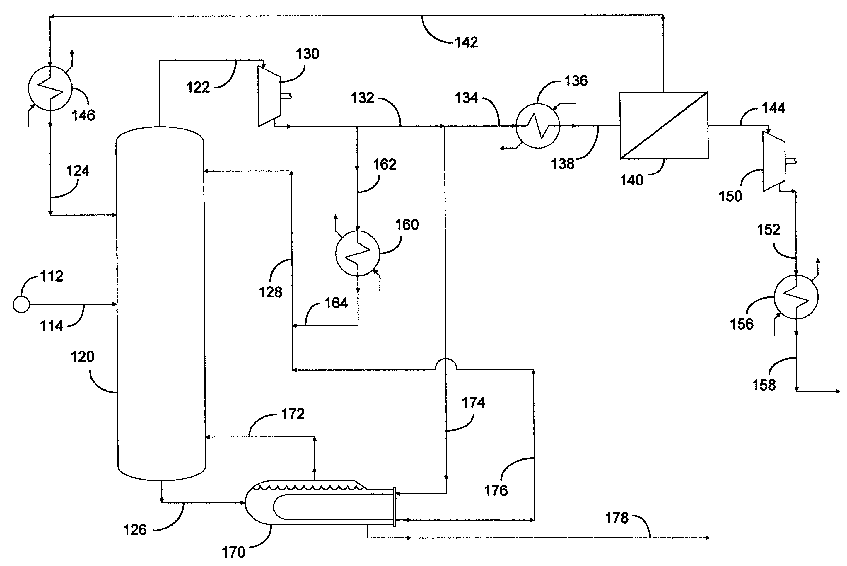
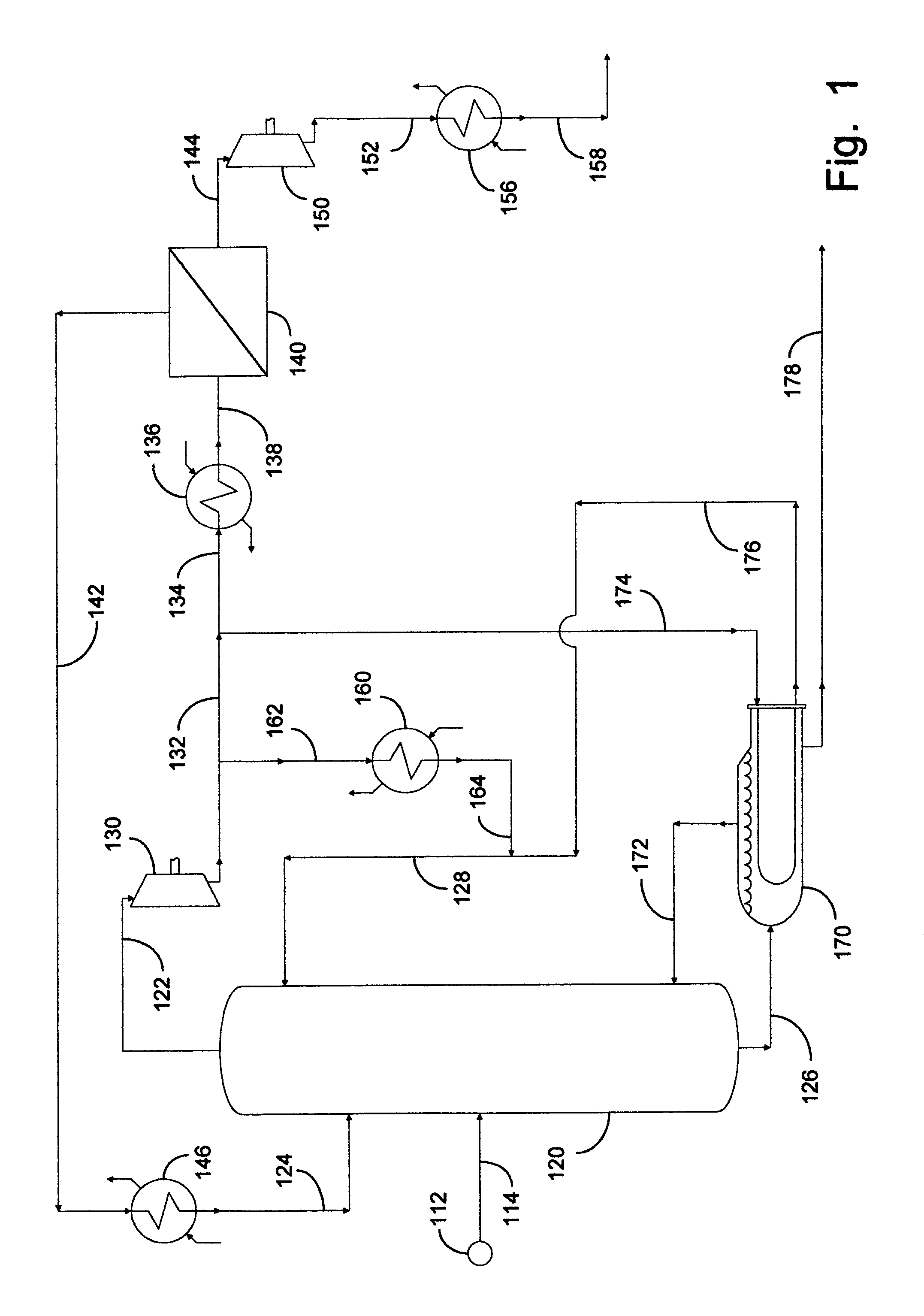
[0069]This example documents an aspect of the preferred embodiment of the invention depicted in FIG. 1. Fractional distillation column 120 was utilized as a C3 splitter with a portion of the compression overhead vapor advantageously distributed into a fugacity-driven membrane separation device 140. Calculations were made using 37.8° C. (100° F.) cooling water in condenser 160. Heat exchangers 136 and 146 were not employed in this example. A temperature gradient of 11.1° C. (20° F.) was assumed across the reboiler in order to set the pressure at the bottom of the column. A pressure drop of 0.1 psi per tray was assumed to determine the compressor suction conditions. This resulted in a column overhead pressure of approximately 140 psia. The liquid rate in the column was chosen so that the separation could be completed with 200 trays, a typical tray requirement for a C3 splitter, and the vapor rate was set so that the column bottoms product met the HD-5 Liquefied Petroleum Gas (LPG) spe...

example 2

[0075]This example documents an aspect of the invention depicted in FIG. 1, utilizing optional heat exchangers 136 and 146 on the membrane feed and / or the nonpermeate in order to limit the amount of vapor being recycled to the column. In this example, calculations were performed at conditions similar to those of Example 1 using heat exchangers 136 and / or 146 on the membrane feed and / or the nonpermeate. It was necessary to cool the membrane feed to from 26.7° to 37.8° C. (80° to 100° F.) or the nonpermeate to approximately 21.1° C. (70° F.) to eliminate vapor recycle to the column. However, this had a small impact on the performance of this propane-propylene separation system. Note that the absolute flow rate of the nonpermeate did not change when heat exchangers 136 and 146 were employed because the nonpermeate flow rate is affected by the feed composition, feed rate, area, and perm-selectivity of the membrane. The heat exchangers affected the phase when the nonpermeate entered the ...

example 3

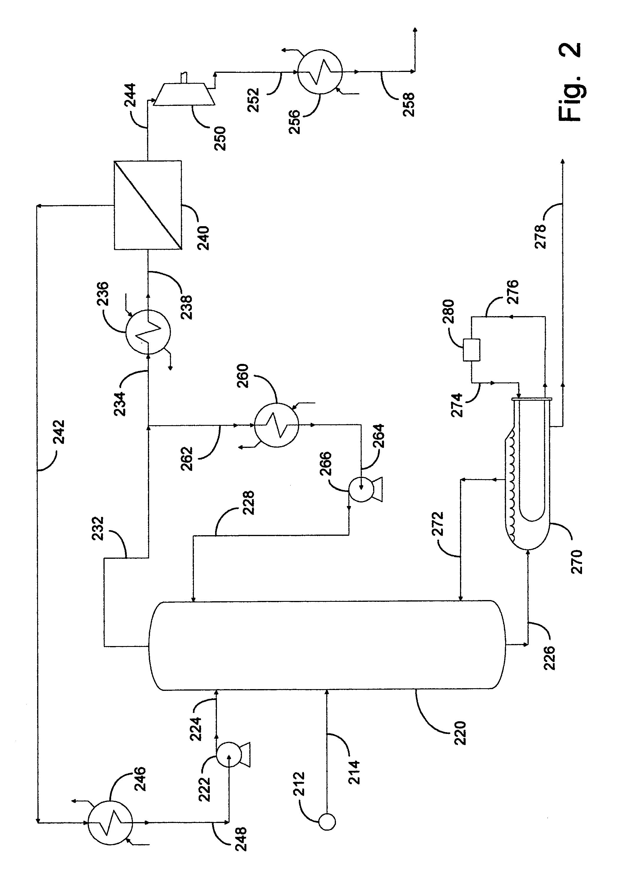
[0077]This example documents an aspect of the preferred embodiment of the invention depicted in FIG. 2. Fractional distillation column 220 was utilized as a C3 splitter with a portion of the overhead vapor advantageously distributed into a fugacity-driven membrane separation device 240. The nonpermeate effluent from separation device 240 was completely liquefied and pressurized by means of pump 222 for recycling into column 220. Calculations were made using 37.8° C. (100° F.) cooling water in condenser 260. This resulted in a column overhead pressure of approximately 230 psia. The liquid rate in the column was chosen so that the separation could again be completed with 200 trays. At the same time, the vapor rate in the column was set so that the column bottoms product met LPG specifications.

[0078]Before the membrane was placed on the apparatus, the existing column diameter was sized to process 10,000 BPD of RGP from source 212 containing 74 percent propylene and 26 percent propane f...


PUM

PropertyMeasurementUnit
volume ratioaaaaaaaaaa
outer diameteraaaaaaaaaa

Abstract

Apparatus and processes are disclosed for economical separation of fluid mixtures. Broadly, apparatus of the invention is an integrated fractional distillation and perm-selective membrane separation apparatus. More particularly, the integrated apparatus comprises a fractional distillation column and one or more membrane device utilizing solid perm-selective membranes. Processes of the invention are particularly useful for simultaneous recovery of a very pure permeate product, a desired non-permeate stream, and one or more distillate products from a fluid mixture containing at least two compounds of different boiling point temperatures.

Description

TECHNICAL FIELD[0001]The present invention relates to processes for recovery of purified products from a fluid mixture by means of an integrated fractional distillation and perm-selective membrane separation apparatus. More particularly, the integrated apparatus of the invention comprises a fractional distillation column and one or more devices using solid perm-selective membranes for recovery of purified products. Apparatus of the invention is particularly useful for simultaneous recovery of a very pure permeate product, one or more products of distillation, and / or a desired non-permeate stream, from a fluid mixture containing at least two compounds of different boiling point temperatures.BACKGROUND OF THE INVENTION[0002]Membranes useful for the separation of gaseous mixtures are of two very different types: one is microporous while the other is nonporous. Discovery of the basic laws governing the selectivity for gases effusing through a microporous membrane is credited to T. Graha...

Claims


Application Information

Patent Timeline
Patent Type & Authority Patents(United States)
IPC IPC(8): B01D15/00B01D3/14B01D3/32B01D53/22C07C7/144
CPCB01D3/14B01D3/322B01D53/229C07C7/144C07C9/08C07C11/06
Inventor COLLING, CRAIG W.HUFF, JR., GEORGE A.PIETSCH, STEPHEN J.
Owner BP CORP NORTH AMERICA INC
Why Eureka
Try Eureka