

Superresolution in microlithography and fluorescence microscopy
a microlithography and fluorescence microscopy technology, applied in the field of scanning optical systems, can solve the problems of reducing the efficiency of light utilization, and reducing so as to minimize the damage of light induced to the specimen, improve the resolution of the optical system, and minimize the effect of light induced bleaching and photolysis
- Summary
- Abstract
- Description
- Claims
- Application Information
AI Technical Summary
Benefits of technology
Problems solved by technology
Method used
Image

Examples
Embodiment Construction
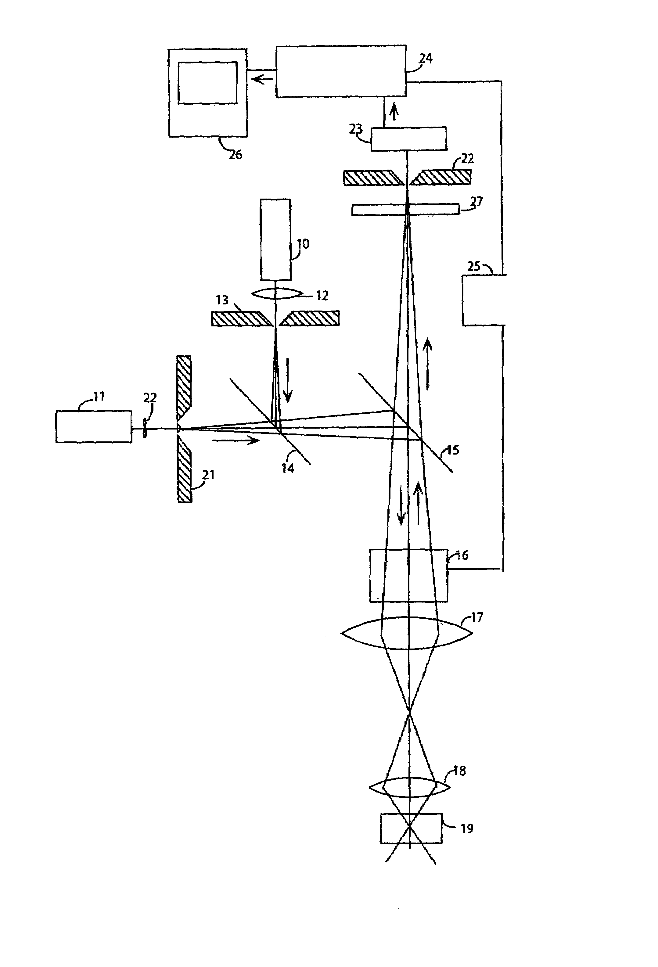
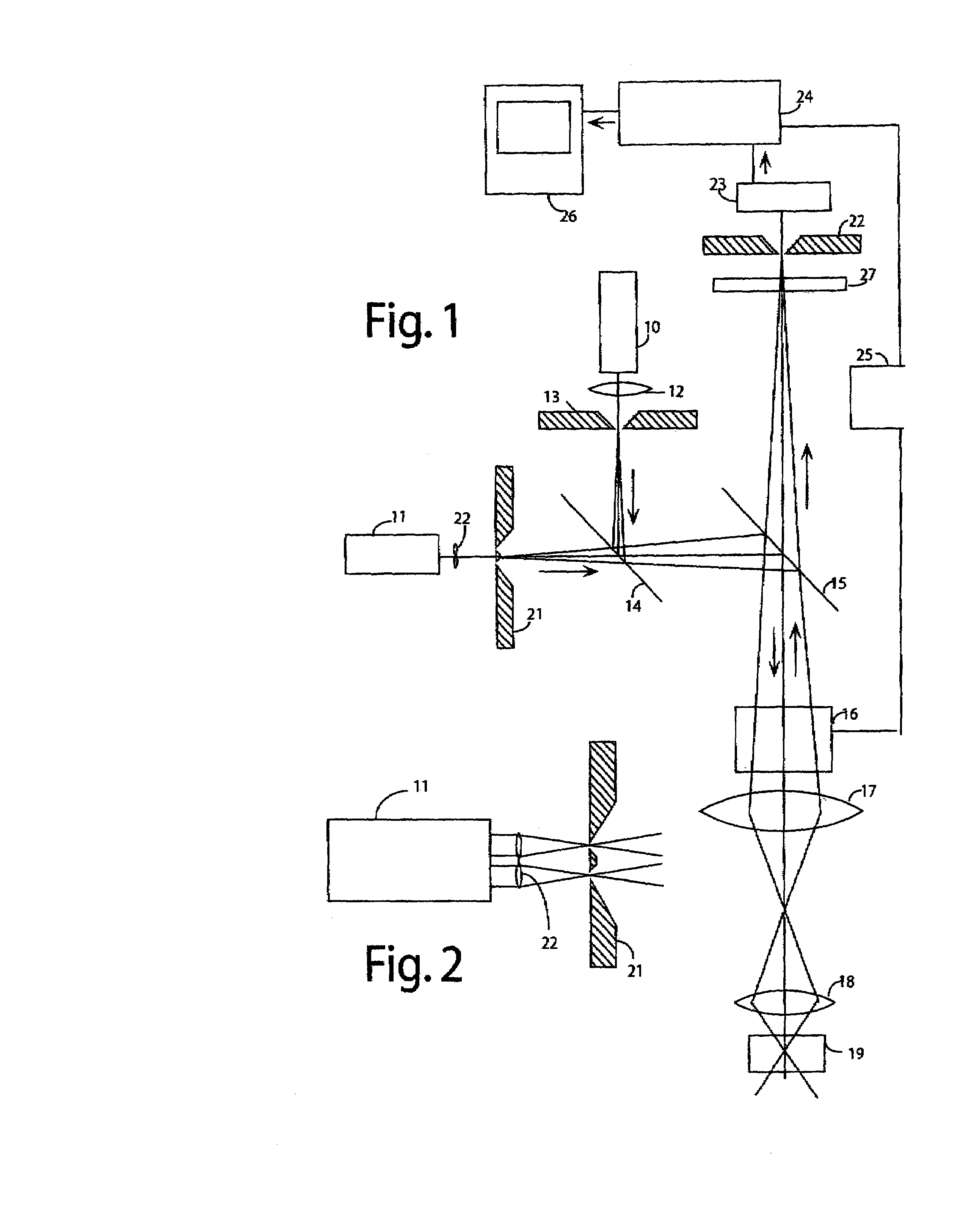
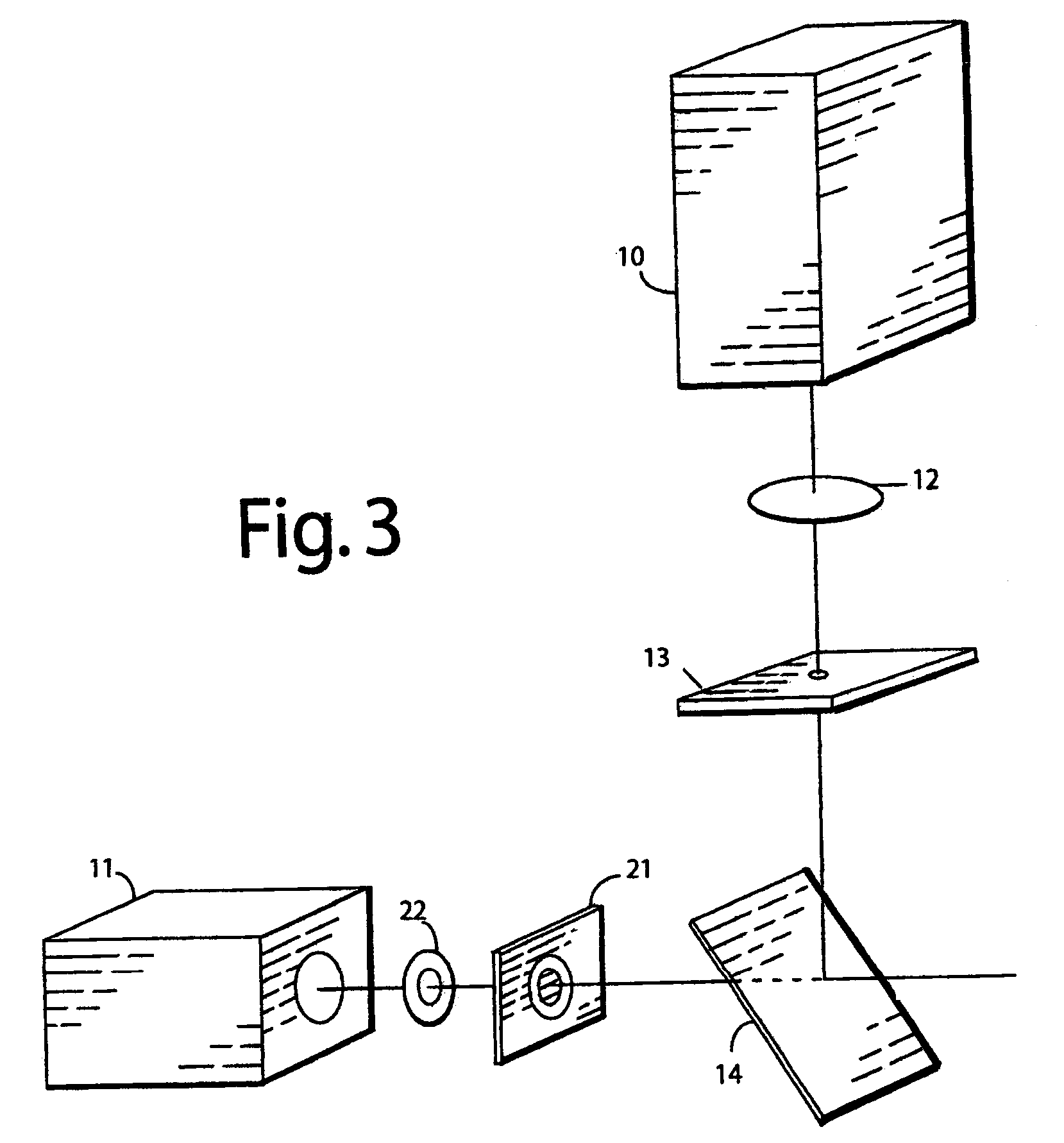
[0038]FIG. 1 shows an embodiment of the present invention employing continuous wave laser illumination. Light from excitation laser 10 is focused by lens 12 onto pinhole aperture 13, and after passing through aperture 13, reflection from dichroic mirror beam splitters 14 and 15 and scanning by beam scanning means 16 (which may be a pair of orthogonal galvanometer powered scanning mirrors) the laser light is imaged by eyepiece 17 and objective 18 on or within the specimen 19 stained with fluorescent molecules excitable by light emitted by laser 10, to form a region of excited fluorescent molecules at the image of pinhole aperture 13. Quenching laser 11, which emits light of a wavelength adapted to quench, by means of stimulated emission, the fluorescent excitation caused by laser 10, is focused by toroidal lens 22 onto annular aperture 21. Light passing through aperture 21 passes through dichroic beam splitter 14, then is reflected by dichroic beam splitter 15 to pass through the bea...
PUM
| Property | Measurement | Unit |
|---|---|---|
| wavelength | aaaaa | aaaaa |
| frequency | aaaaa | aaaaa |
| frequency | aaaaa | aaaaa |
Abstract
Description
Claims
Application Information